Suture Method

a suture and body technology, applied in the field of surgical suturing methods, can solve the problems of increasing scarring, time-consuming suturing, and loop sutures leaving scars where they penetrate the skin,

a suture and body technology, applied in the field of surgical suturing methods, can solve the problems of increasing scarring, time-consuming suturing, and loop sutures leaving scars where they penetrate the skin,

US20070208377A1Inactive Publication Date: 2007-09-06ETHICON INC

Image

  • Suture Method
  • Suture Method
  • Suture Method

Examples


example 2

[0118] Seven incisions were made at various locations on each of three dogs. The length of the incisions ranged from ½ inch to 4 inches and the depth of the incisions from the dermis to the muscular level. The incisions were closed with barbed sutures made from monofilament PDS (polydioxanone) size 0 and conventional sutures according to the following scheme with the locations randomized:

TABLE 2Barbed SutureTissue LevelMethodConventional Suture MethodDermisAlpha, ZigzagSimple interrupted loop stitches[2-0 nylon, 2-0 silk]SubcuticularCorkscrewSimple continuous loop stitches[3-0 PDS]SubcutaneousCorkscrewSimple continuous loop stitches[3-0 PDS]MuscularCorkscrewSimple continuous loop stitches[3-0 PDS]

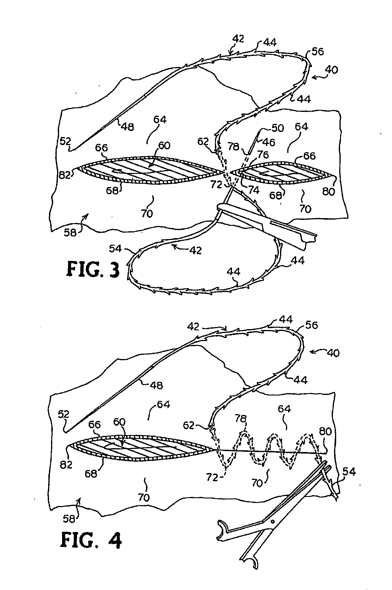
More than one alpha-shaped stitch was used for longer incisions.

[0119] The dogs were housed for two weeks. Daily clinical and necropsy observations were performed on all surgical sites. With the exception that three of six sites closed by nylon sutures had some sutures chewed out by the...


PUM


Abstract

A method is provided for performing a procedure to reposition a portion of a breast using a suture including a plurality of barbs. The barbs on a first portion of the suture adjacent a first end of the suture permit movement of the suture through tissue in a direction of movement of the first end and prevent movement of the suture through tissue in a direction opposite the direction of movement of the first end. The barbs on a second portion of the suture adjacent a second end of the suture permit movement of the suture through tissue in a direction of movement of the second end and prevent movement of the suture through tissue in a direction opposite the direction of movement of the second end. The method comprises the steps of inserting the first end of the suture through a first insertion point and causing the first portion of the suture to engage a tissue, inserting the second end of the suture through the first insertion point and advancing the second end of the suture through breast tissue to a first exit point located on the breast caudally of the first insertion point, and manually grouping and advancing the breast tissue relative to the suture towards the first insertion point to reposition a portion of the breast tissue.

Description

CROSS-REFERENCES [0001] This application is a continuation of U.S. patent application Ser. No. 11 / 307,521, filed Feb. 10, 2006, currently pending, which is a divisional application of U.S. patent application Ser. No. 10 / 065,256, filed Sep. 30, 2002, now U.S. Pat. No. 7,056,331, which is a continuation-in-part application of U.S. patent application Ser. No. 09 / 896,455, filed Jun. 29, 2001, now U.S. Pat. No. 6,599,310. All of these above-listed applications are incorporated herein by reference.BACKGROUND [0002] This invention relates generally to a method for joining bodily tissue in surgical applications and wound repair, and more particularly to a surgical suturing method for joining bodily tissue using a suture having a plurality of barbs which permit the suture to be pulled through the tissue in one direction but resisting movement of the suture relative to the tissue in the opposite direction. [0003] Surgical or accidental wounds are typically closed with a length of filament int...

Claims


Application Information

Patent Timeline
06 Sep 2007
Publication
US20070208377A1
IPC
A61B17/04; A61B; A61B17/00; A61B17/06; A61B17/08; A61B17/11
CPC
A61B17/00234; A61B2017/1135; A61B17/04; A61B17/06061; A61B17/06166; A61B17/062; A61B17/1114; A61B17/1146
Inventors
KAPLAN, ANDREW; RUFF, GREGORY L.