KVM switching system

a switching system and network technology, applied in the field of network kvm system, can solve the problems of wasting resources, high operation costs, and inability to provide the great bandwidth of large networks, and delay the respons

Inactive Publication Date: 2007-09-06
ATEN INT CO
View PDF7 Cites 24 Cited by
  • Summary
  • Abstract
  • Description
  • Claims
  • Application Information

AI Technical Summary

Benefits of technology

[0015] Accordingly, the present invention provides a KVM switch that can monitor the booting status value from the 1 / O port 80 of the first computer and automatically sends out an interruption instruction to interrupt the first computer when the first computer is in a booting state. Therefore, even when the network connection lags, the first computer can still be accessed properly in real time.

Problems solved by technology

Such structure resulted in high operation costs and wasted resources.
However, the great bandwidth necessary for large networks cannot often be provided, delaying response between computers 101, 102 and 103 and second computer 105.
Such delayed response causes great inconvenience for maintenance staffs.
Moreover, when the computer is broken during booting and no any error information is shown in the display of the computer 105, the remote maintenance staff cannot understand the real reason of the computer broken through the conventional IKVM technology.
Therefore, a replacement component may not be prepared in advance by the remote maintenance staff.
Then, the maintenance staff goes back to his maintenance office again to prepare this replacement component, which will consume a lot of time.

Method used


Image

  • KVM switching system
  • KVM switching system
  • KVM switching system

Examples


Embodiment Construction

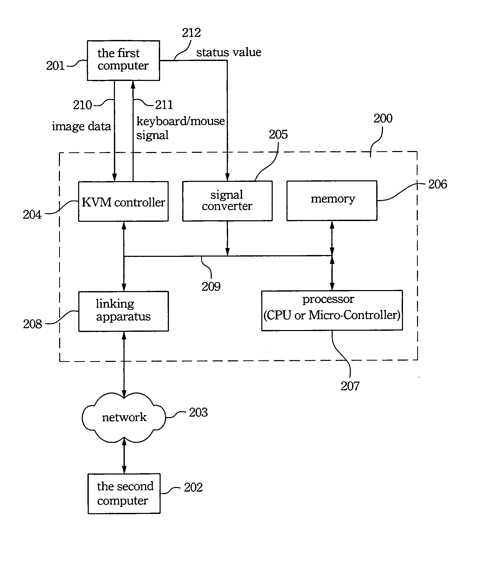
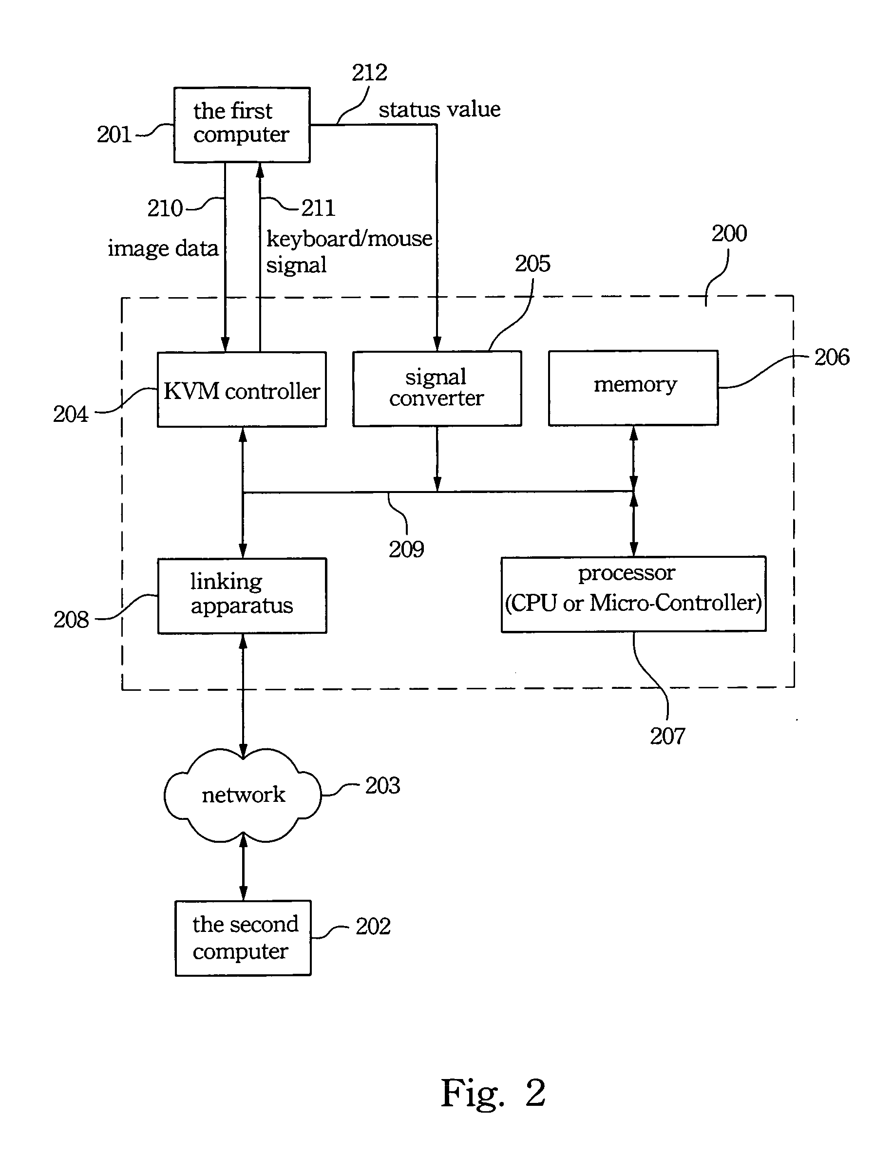
[0023]FIG. 2 is a schematic diagram of a KVM switch 200 according to a preferred embodiment of the present invention. The KVM switch 200 of the present invention can connect to a plurality of first computers and switch one of these first computers to connect with the second computer 202 via the network 203. The KVM switch 200 communicates with a second computer 202 through the network 203, such as a LAN, a WAN or the Internet. In FIG. 2, the first computer 201 is switched to connect with the second computer 202 through KVM switch 200. The keyboard, the monitor and the mouse, not shown in FIG. 2, of the second computer 202 can control the first computer 201 through the KVM switch 200. For example, in an embodiment, when the first computer 201 is selected, the image data 210 from the selected first computer 201 is sent to the second computer 202 through the KVM switch 200 and is displayed by the second computer 202. Therefore, a user can see this image in the second computer 202 and, ...


PUM


Abstract

The present invention provides a KVM switching system including a KVM controller, a signal converter, a processor and a linking apparatus. The booting status signal of a computer is sent to the signal converter, which then converts the status signal. The converted status signal is sent to the processor, which then determines whether or not the computer is in a process of asking a user to enter BIOS setting mode. The processor automatically controls the KVM controller to issue an interruption instruction to the computer when the computer is in the process of asking a user to enter BIOS setting mode.

Description

FIELD OF THE INVENTION [0001] The present invention relates to a KVM system, and more particularly, to a network KVM system. BACKGROUND OF THE INVENTION [0002] The exponential growth of computer systems and network software allow people to utilize networks to search for and gather information from other computers. Conventionally, control of each computer required a monitor, a keyboard and a mouse. That is, each computer needed at least a monitor, a keyboard and a mouse. Such structure resulted in high operation costs and wasted resources. A KVM (keyboard, video monitor and mouse) switch has been used to resolve this expense. [0003] An example of the traditional KVM switch is shown in FIG. 1. A KVM switch 100 can connect to and switch between a plurality of computers 101, 102 and 103 through a network 104. The network 104, such as a LAN, WAN, or Network, provides a communication path for a second computer 105 and computers 101, 102 and 103. Through the switching of the KVM switch 100...

Claims


Application Information

Patent Timeline
Patent Type & Authority Applications(United States)
IPC IPC(8): G06F13/38
CPCG06F11/2294
Inventor LIU, CHIEN-HSING
Owner ATEN INT CO
Why Eureka
Try Eureka