Lathe hobbing tool

a hobbing tool and lathe technology, applied in the direction of gear teeth, manufacturing tools, manufacturing apparatuses for gear teeth, etc., can solve the problems of machining errors, production rate of components, and inability to perform hobbing operations on a 3-axis cnc lath

Inactive Publication Date: 2007-09-13
WILLIAMS MARK +1
View PDF11 Cites 20 Cited by
  • Summary
  • Abstract
  • Description
  • Claims
  • Application Information

AI Technical Summary

Benefits of technology

[0007] The present invention is a hobbing tool that connects to a CNC lathe for performing a hobbing operation on a workpiece mounted in the lathe. It includes a drive end for mounting to a tool station of a turret of the lathe and for being driven by the lathe and a hobbing end having a hob drive shaft for supporting and driving a hob to machine a

Problems solved by technology

Hobbing machines are complex machines that provide for numerous adjustments to accommodate different sizes of workpieces, different sizes of hobs, different pitches of teeth, etc.
This increases the production rate of the components and can decrease errors in machining, such as can be caused when transferring the workpiece from one machine to another.
Previously, it has not been possible to perf

Method used


Image

  • Lathe hobbing tool
  • Lathe hobbing tool
  • Lathe hobbing tool

Examples


Embodiment Construction

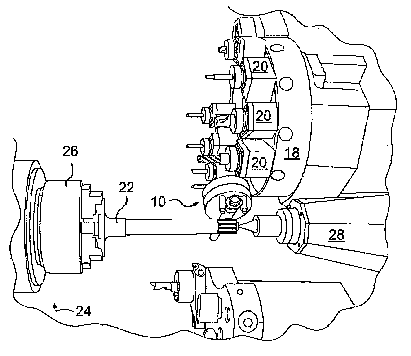
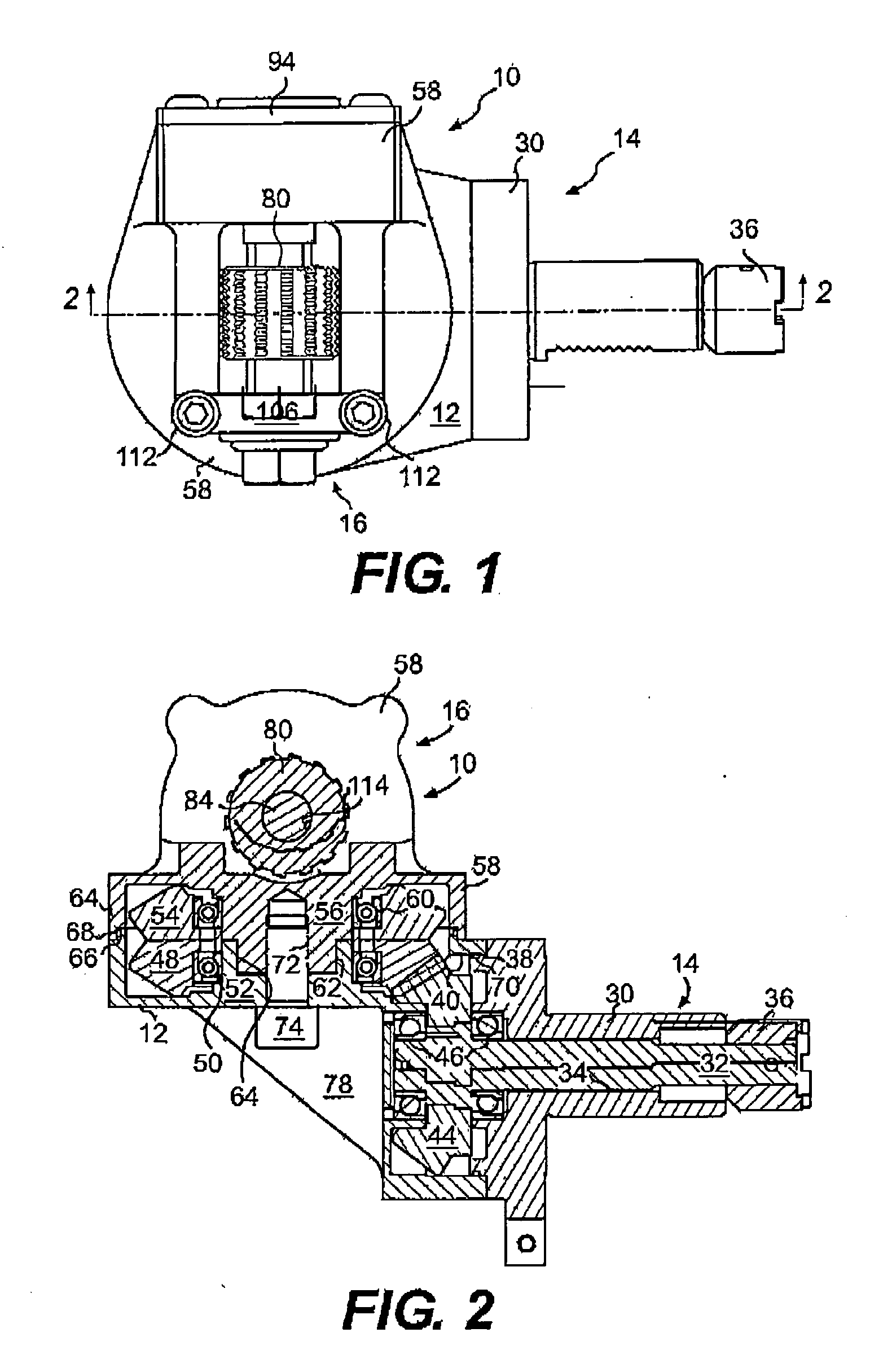
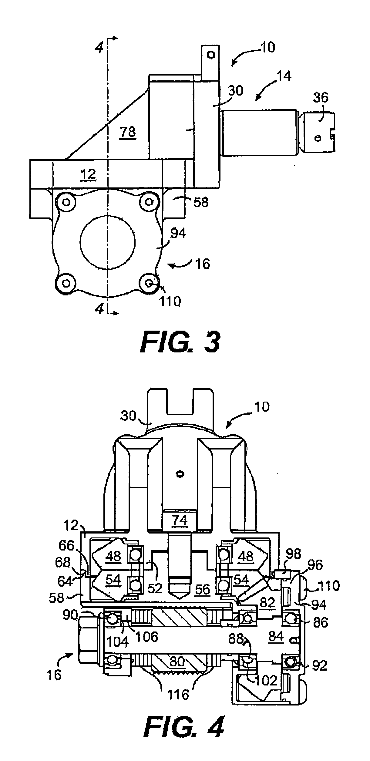
[0019] The lathe hobbing tool 10 of the present invention is shown in FIGS. 1-8. It includes a main housing 12 to which is connected a drive end 14 for mounting to a tool station 20 of a lathe turret 18 in a known manner. The lathe turret 18 includes a number of tool stations 20 for receiving both live and stationary tools and also includes an internal drive system for driving live tools. Rotation of the turret 18 allows a desired one of the number of tools mounted at the tool stations to be indexed for a machining operation on a workpiece 22 mounted in lathe 24 (see FIGS. 7-8). On the lathe 24 shown, the workpiece is mounted between chuck 26 and tailstock 28. The chuck 26 is connected to the lathe's drive system for driving (rotating) the workpiece 22 in a known manner.

[0020] The drive end 14 includes a drive housing 30. The drive housing includes a flange 38 for mounting in a bore 40 of the main housing 12. The flange accurately positions the drive end 14 in the main housing 12. ...


PUM

PropertyMeasurementUnit
Angleaaaaaaaaaa
Speedaaaaaaaaaa

Abstract

A hobbing tool connects to a CNC lathe for performing a hobbing operation on a workpiece mounted in the lathe. It includes a drive end for mounting to a tool station of a turret of the lathe and for being driven by the lathe and a hobbing end having a hob drive shaft for supporting and driving a hob to machine a portion of the workpiece mounted in the lathe. The hob drive shaft is operatively connected to the drive end so that the hob drive shaft can be rotationally driven by the lathe. The hobbing end is connected to the drive end with a rotationally adjustable coupling which allows a lead angle of the hob shaft to be adjusted with respect to the workpiece.

Description

[0001] This application claims priority to U.S. Provisional Patent Application 60 / 671,521, filed Apr. 15, 2005, entitled Lathe Hobbing Tool and by the same inventors as the present application, the entirety of which provisional application is incorporated by reference herein.BACKGROUND OF THE INVENTION [0002] The present invention relates to a tool for use with a lathe that can perform hobbing on a workpiece mounted in the lathe. [0003] Hobbing is a well known process for creating gear teeth and / or splines on a component (workpiece). This is done in a hobbing machine which uses interchangeable hobs to cut the teeth into components. Hobbing machines are complex machines that provide for numerous adjustments to accommodate different sizes of workpieces, different sizes of hobs, different pitches of teeth, etc. Hobbing is an effective, efficient process for creating strong, precisely formed and positioned teeth on a workpiece. The hob is essentially a cutting tool generally in the form...

Claims


Application Information

Patent Timeline
IPC IPC(8): B23B27/00
CPCB23B11/00B23B29/32B23F5/22B23F9/082B23F17/00Y10T29/5114B23F21/16B23F23/1206B23F23/1243Y10T29/5155B23F21/005
Inventor WILLIAMS, MARKGOETHE, BRET
Owner WILLIAMS MARK
Why Eureka
Try Eureka