
Roller support arrangement for top and bottom display holder

a support arrangement and display holder technology, applied in the field of multichambered extrusions, can solve the problems of difficult assembly and inability to work as a holder on the bottom of a substrate, and achieve the effect of longer length

Inactive Publication Date: 2007-09-13
ROSE DISPLAY
View PDF3 Cites 28 Cited by
  • Summary
  • Abstract
  • Description
  • Claims
  • Application Information

AI Technical Summary

Benefits of technology

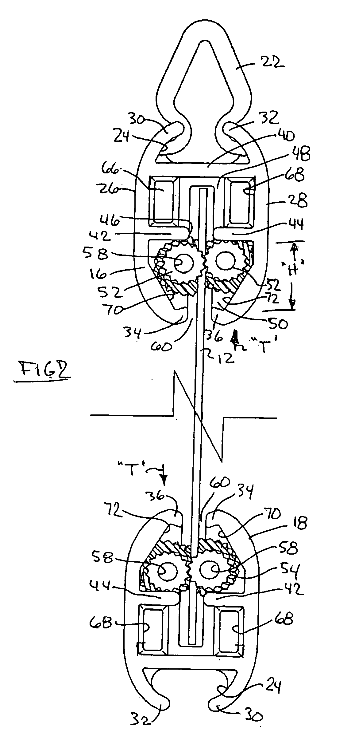
[0015] Insertion and removal of a poster or substrate from the pair of upper and lower elongated extruded support housings is accomplished by longitudinal movement of that poster substrate relative to the pair of elongated extruded support housings. It is the combination of the round cross-sectional shape of the rollers and the converging angled geometry of the space that prevents removal of a substrate by a force perpendicular to the extrusion on the substrate. The multiple plane nonlinearity of the rollers guarantees their interfering contact with the substrate. The rollers are free to rotate towards the opening, and as they do so rotate, the space (wedge) gets tighter, thus providing an increasingly stronger grip on the substrate.
[0017] The lowermost elongated chamber in the elongated extruded support arrangement has a pair of opposed facing walls which are tapered inwardly with respect to one another. These walls define a lower side against which each respective internal roller is maintained and pressed. Such tapered walls prevent removal of the substrate and its falling or being pulled transversely out from the elongated housings.
[0018] In a further embodiment of the present arrangement, the internal flexible rollers are provided with a multi-dimensional convolution by being slightly longer than the length of the extruded elongated housing in which they are placed. When the end caps are pressed against the ends of the internal rollers once they are inserted within the lower chamber, the end caps will put a compressive force on those pair of internal rollers forcing them to twist / convolute and become nonlinear, ensuring interaction with the substrate to be held.
[0019] In yet a further embodiment of the present invention, the elongated extrusion support housings may be curved somewhat, so as to provide a slight curve to the poster or substrate being held between a pair of elongated supports, and also, to eliminate the need for a pre-curved wire or insert within each internal roller. In fact, in such a case, the internal rollers are shorter longitudinally than the arc length of the curved elongated extruded support arrangement.
[0021] Thus the present invention shows a hollow, elongated extruded poster grasping housing which is capable of lockably supporting a large poster or substrate, also having a lowermost housing extrusion to support and hang down upon the lower edge of that poster or substrate therebetween. The rollers arranged within each elongated extrusion are dimensioned such that they do not pass over each other and that, arranged into a pair of interacting convolutions, must interfere with the space in line with the center slot arranged between the sidewalls of the elongated support housing(s). This interference prevents the poster or substrate from becoming loose from each elongated support housing when it is pulled upon or set in place, thereby denying gravity its affects on that substrate.

Problems solved by technology

The assembly is difficult because the user must roll strips of acetate and insert them into a hollow chamber.
It will not work as a holder on the bottom of a substrate.

Method used


Image

  • Roller support arrangement for top and bottom display holder
  • Roller support arrangement for top and bottom display holder
  • Roller support arrangement for top and bottom display holder

Examples


Embodiment Construction

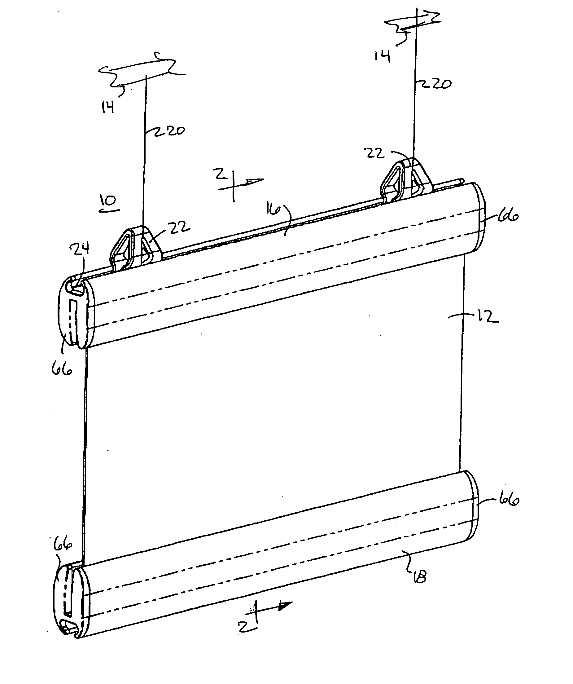
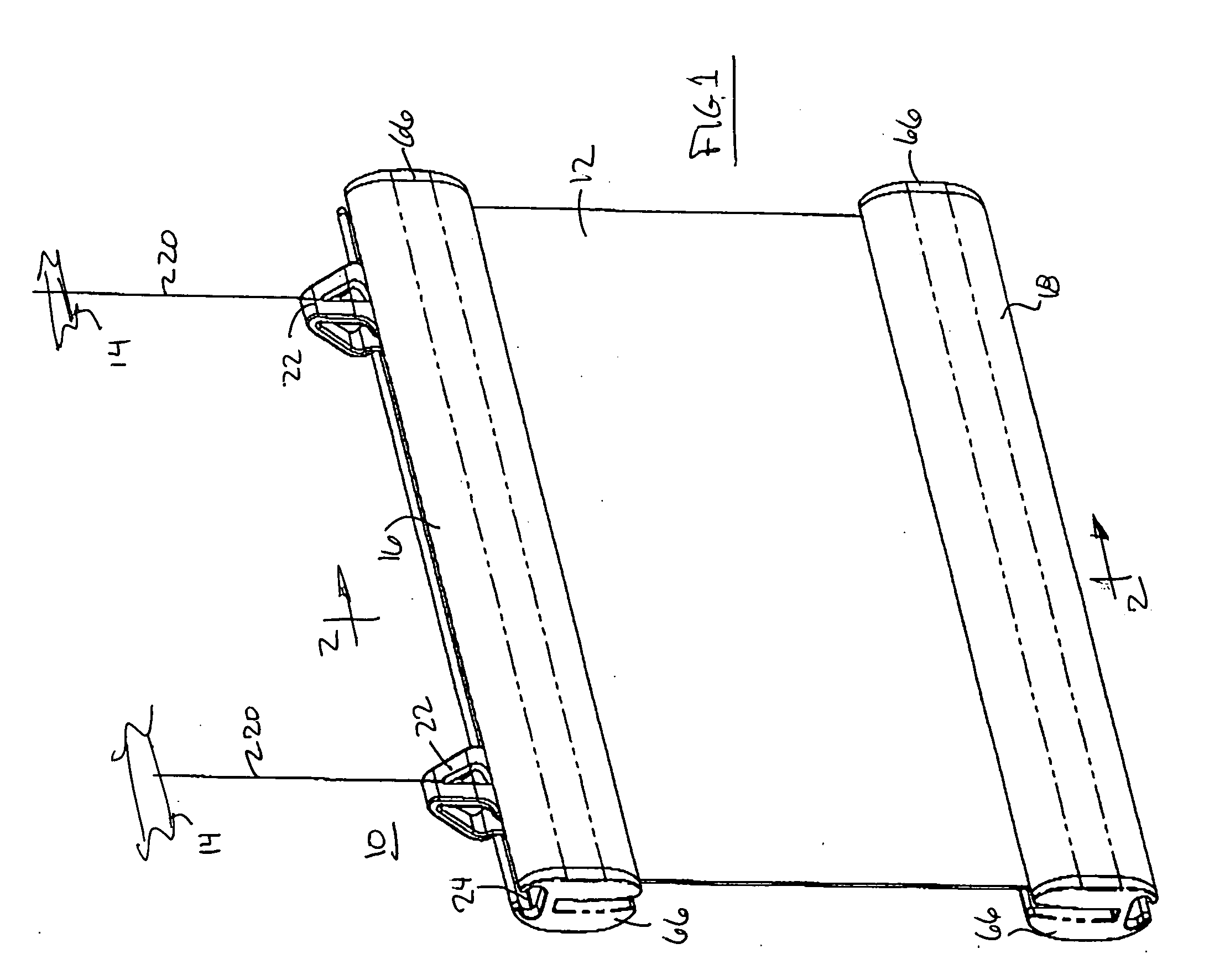
[0034] Referring now to the drawings in detail, and particularly to FIG. 1, there is shown the present invention which comprises an elongated, multi-chambered extrusion support arrangement 10 which is configured to support a large poster substrate 12 from an overhead support, such as a ceiling rail 14 or the like. The support arrangement 10 of the present invention in a preferred embodiment thereof, comprises an upper, elongated, extruded, multi-chambered housing 16 and a second or lower, elongated multi-chambered housing 18. The poster substrate 12 is fixedly carried between the upper and the lower elongated housings 16 and 18. The upper housing 16 may be attached to the overhead support ceiling rail 14 by a pair of overhead support lines 20 connected therebetween. The lower end of each overhead support line 20 is attached to a support clip 22 which slidably engages a support clip channel 24 arranged on one elongated side of each of the elongated housings 16 and 18, as shown in FIG...


PUM


Abstract

A support arrangement for supporting a poster from an adjacent or overhead member. The arrangement comprises an elongated first extruded housing on at least one side of the poster. The housing comprises three chambers defined by opposing sidewalls with a perpendicular connecting bridge and one set of opposing lips. The first and second elongated lips and the lower edge of the sidewalls define an elongated holding third chamber having tapered sidewalls comprising a wedge-shaped elongated chamber. The substrate to be supported may be inserted longitudinally through an elongated space between the tapered sidewalls. A pair of elongated, flexible rollers are arranged within that elongated wedge-shaped holding third chamber. The rollers are of non-linear configuration in at least two planes. The non-linear shape to the rollers ensures contact with the substrate even when the housing is used upside down on the bottom of a substrate. The tapered walls of the wedge-shaped chamber increasingly pinch the rollers together as gravity or another pulling force acts upon the substrate, thus holding the substrate tighter and denying gravity, or any other transverse pulling force, its effect on the substrate and housing.

Description

BACKGROUND OF THE INVENTION [0001] 1. Field of the Invention [0002] This invention relates to multi-chambered extrusions which are to be utilized for rigid support of a display poster or substrate from a ceiling or an overhead support or the like. [0003] 2. Prior Art [0004] The prior art cites the use of rollers in a holder arranged at the top of a substrate. The present invention relates to how an assembly is modified to allow the holder to also work on the bottom of the substrate. The key to using rollers with a bottom holder is to ensure their interaction with the substrate. The present invention, from a user's perspective, is passive, the support arrangement functioning similarly on both the top and bottom of the substrate being supported from an overhead or on a wall. [0005] U.S. Pat. No. 6,512,094 to Dilworth relates to a textile hanging system which requires many steps, including opening and closing a banner textile holder over the textile substrate and the pushing end caps o...

Claims


Application Information

Patent Timeline
IPC IPC(8): G09F7/22
CPCG09F2007/186G09F7/18
Inventor STOVER, REBECCA C.PITCHER, DAVID E.BURROUS, THOMAS P.ROSE, SIDNEYSTENFORS, ALAN L.
Owner ROSE DISPLAY
Learn More