Method and apparatus for supply of low-btu gas to an engine generator

a low-btu gas and engine generator technology, applied in the direction of combustible gas production, combustible gas purification/modification, machines/engines, etc., can solve the problems of inability to achieve low-btu fuel methods, limited gaseous fuel supply methods to engine generator systems, and failure to develop pressure-based carburetion methods for low-btu gas

Inactive Publication Date: 2007-09-13
ENERGY & ENVIRONMENTAL RES CENT FOUNDATIO
View PDF25 Cites 15 Cited by
  • Summary
  • Abstract
  • Description
  • Claims
  • Application Information

AI Technical Summary

Benefits of technology

[0010]U.S. Pat. No. 5,070,851 by Janisch discloses a traditional pressure-based air-gas mixer or carburetor intended for low-Btu gas specific to Briggs and Stratton engines, which are typical small engines used for lawnmowers and other small engine applications. The object of the invention is to supplement gas

Problems solved by technology

Existing methods of providing gaseous fuels to engine generator systems are limited to gases having heating values of 500 Btu/scf and greater.
These methods are not feasible with low-Btu fuels.
Although fuel injection systems have been disclosed for low-Btu gas control, the development of pressure-based carburetion methods for low-Btu gas has not been successful.
The significant volume of additional gas to be mixed with air in a low-Btu carburetor cannot be addressed with high-Btu geometry carburetors.
It is undesirable and impracticable to interrupt the continuous production of gas.
Methods for adapting low-Btu gas (producer gas, biomass gas, or syngas) to engine generator systems have remained limited to manual valve mixing or electronic control.

Method used


Image

  • Method and apparatus for supply of low-btu gas to an engine generator
  • Method and apparatus for supply of low-btu gas to an engine generator
  • Method and apparatus for supply of low-btu gas to an engine generator

Examples


Embodiment Construction

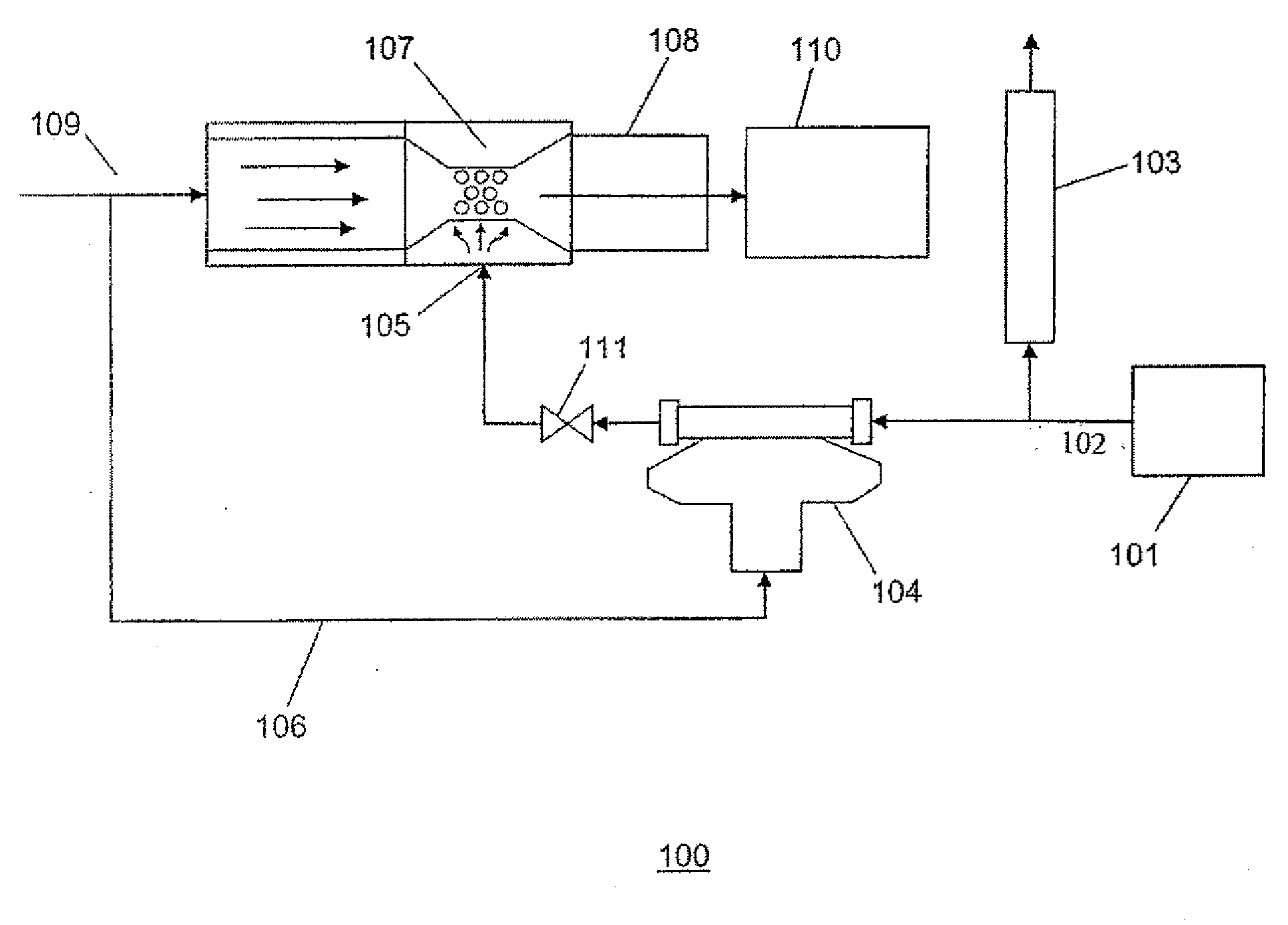
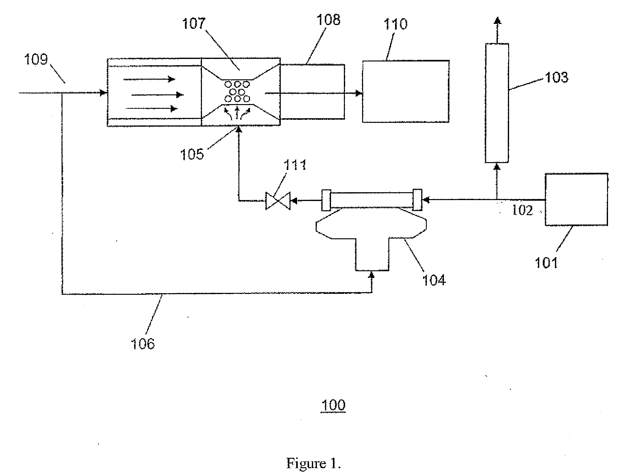
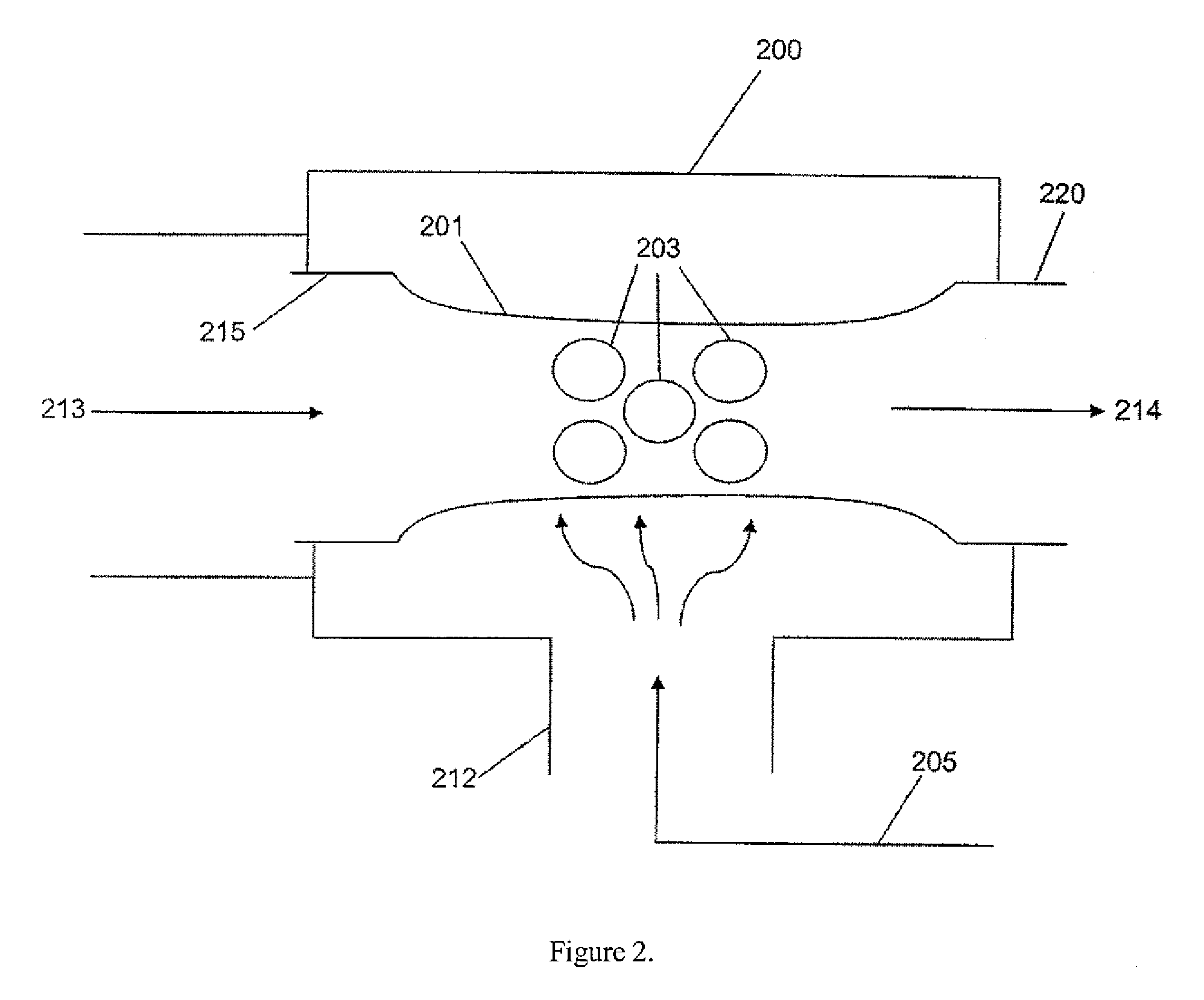
[0014]These and other needs in the art are addressed by the presently disclosed carburetion system. The carburetion system comprises a low-Btu gas inlet, a gas outlet, a zero-pressure regulator, and at least one pressure-based air-gas mixer capable of maintaining a volumetric air-to-gas ratio of no more than 2:1. In embodiments, the gas outlet comprises a flare device. In embodiments, the zero-pressure regulator is coupled to a load control valve. In embodiments, the carburetion system further comprises a low-Btu gas source. In embodiments, the low-Btu gas source is a continuous gas source. In embodiments, the low-Btu gas source is a gasifier. In embodiments, the low-Btu gas source is a biomass gasifier. In embodiments, the low-Btu gas source is a gas-producing oil well. In embodiments, the carburetion system comprises a plurality of air-gas mixers. In certain arrangements, the plurality of air-gas mixers are connected in series. In embodiments, the at least one pressure-based air-g...


PUM


Abstract

A carburetion system and method for adapting a low-Btu gas source with a low-Btu gas consumer. Pressure-based air-gas mixers geometrically appropriate for the carburetion system and method. The carburetion system comprises a low-Btu gas inlet, a gas outlet, a zero-pressure regulator, and at least one pressure-based air-gas mixer capable of maintaining a volumetric air to low-Btu gas ratio of no more than about 2:1. The method comprises diverting a low-Btu gas to a gas outlet when the gas consumer is off. The method further comprises, during operation of the consumer, diverting low-Btu gas to a zero-pressure regulator in order to balance low-Btu gas pressure with air pressure, passing low-Btu gas to at least one pressure-based air-gas mixer capable of maintaining a volumetric air to low-Btu gas ratio of no more than about 2:1, mixing the low-Btu gas with air in the at least one pressure-based air-gas mixer to form an air-gas mixture, and sending the air-gas mixture to the consumer. A venturi air-gas mixer comprising at least one venturi gas intake and at least one venturi air intake wherein the at least one venturi gas intake has a cross-sectional area at least equal to the cross-sectional area of the at least one venturi air intake whereby the venturi air-gas mixer is capable of maintaining a volumetric air-to-gas ratio of no more than about 1:1.

Description

CROSS-REFERENCE TO RELATED APPLICATIONS[0001]This application claims benefit from provisional patent application Ser. No. 60 / 780,704 filed Mar. 9, 2006, which is hereby incorporated herein by reference in its entirety for all purposes as if reproduced in full below.STATEMENT REGARDING FEDERALLY SPONSORED RESEARCH OR DEVELOPMENT[0002]Not applicable.BACKGROUND[0003]1. Field of the Invention[0004]This invention relates generally to the field of gaseous fuel carburetion. More specifically, the invention relates to a low-Btu gas carburetion system and method for use with a consumer such as an engine generator that may be operated intermittently.[0005]2. Background of the Invention[0006]The production of energy is critical to the economic survival of developed nations. The use of recoverable sources of energy provides advantages to process industries in terms of efficiency and economy and may decrease negative environmental impact. Successful utilization of low-Btu gases for fuel may prov...

Claims


Application Information

Patent Timeline
IPC IPC(8): F02B43/00C10J1/00
CPCC10J1/20
Inventor SCHMIDT, DARREN D.
Owner ENERGY & ENVIRONMENTAL RES CENT FOUNDATIO
Why Eureka
Try Eureka