Twin lubrication tank filling system

a filling system and lubrication oil technology, applied in the direction of lubricant transfer, lubrication elements, thin material processing, etc., can solve the problems of interfering with the refilling of the tanks, unable to ensure that both tanks are filled with lubrication, and difficulty in ensuring that both tanks are lubricated without overfilling one tank

Inactive Publication Date: 2007-09-13
HAMILTON SUNDSTRAND CORP
View PDF6 Cites 5 Cited by
  • Summary
  • Abstract
  • Description
  • Claims
  • Application Information

AI Technical Summary

Benefits of technology

[0006] The invention comprises a twin lubrication oil tank filling system with a single oil fill port that prevents overfilling a primary oil tank and a secondary oil tank. A gravity fill system directs oil to flow primarily into the secondary oil tank. A float valve for the secondary oil tank closes when the lubrication oil reaches a full level in the secondary tank and forces additional oil flow to pour into the primary oil tank. A float valve for the primary tank closes when the lubrication oil reaches a full level in the primary tank, and any additional oil flow spills out the oil fill port. The float valves may comprise a special float valve that has a generally annular float that slides upon a generally cylindrical support member with oil fill holes. As the oil level rises, so does the float until it covers the oil fill holes, thereby terminating flow.

Problems solved by technology

When a gearbox design requires separate oil systems for the gearbox and the generator, each system with a separate oil tank but with a common oil fill port, it is difficult to insure that both tanks fill with lubrication without overfilling one tank or the other.
A problem with this design has been that the float valves with internal floats to perform the tank closing operations do not perform the closing operation as required.
In particular, although the valve floats generally close the tanks upon filling as required, they tend to stick in the closed position after shutting, thereby interfering with refilling of the tanks.

Method used


Image

  • Twin lubrication tank filling system
  • Twin lubrication tank filling system
  • Twin lubrication tank filling system

Examples


Embodiment Construction

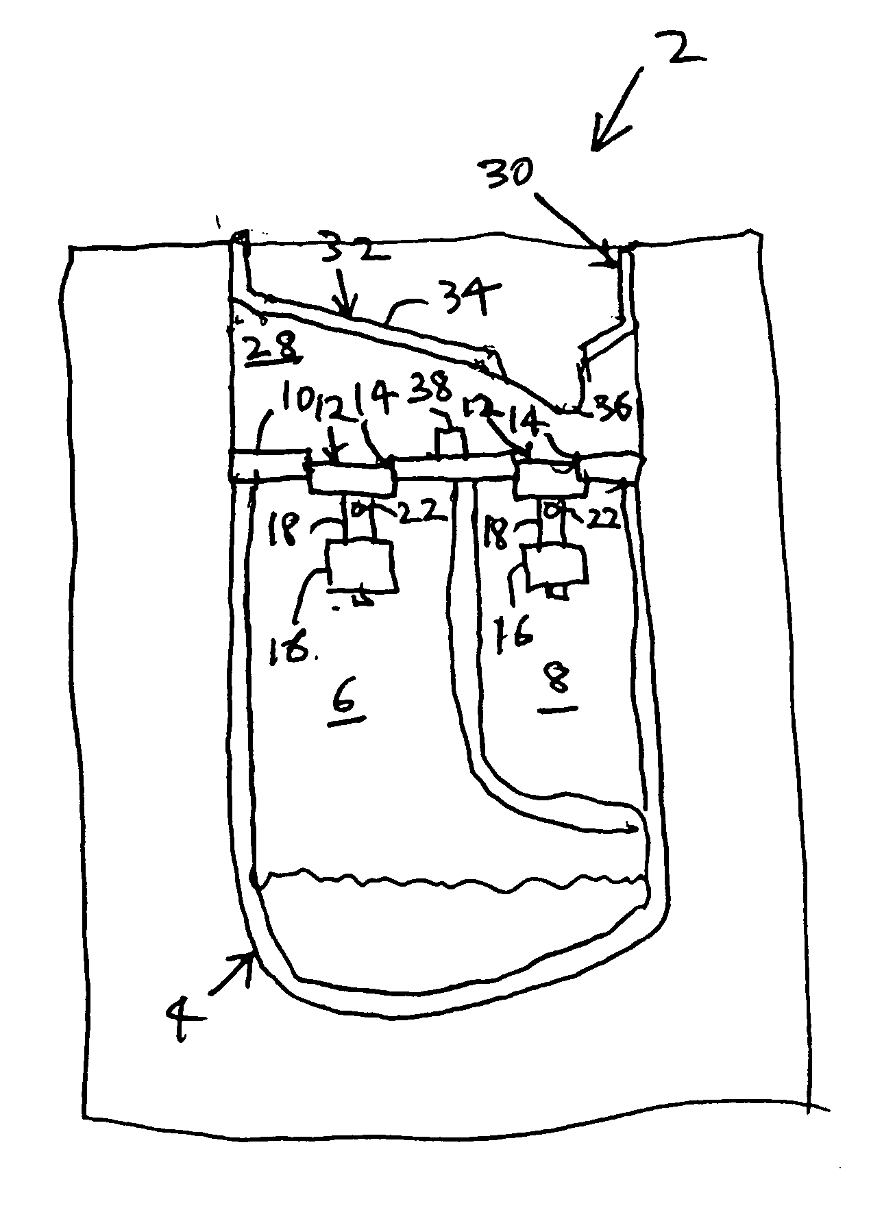
[0012]FIG. 1 is a cut-away side view of machinery, such as a gearbox 2, that incorporates a twin lubrication oil tank filling system 4 according to one possible embodiment of the invention. By way of example as illustrated, the gearbox 2 is designed for an aeronautical APU, but the gearbox 2 may be configured for any other application where it may be used to couple a prime mover to a load. The twin tank filling system 4 comprises a primary oil tank 6 to supply oil for the gearbox 2 and a secondary oil tank 8 to supply oil to at least one load or accessory attached to the gearbox 2, such as a generator (not shown).

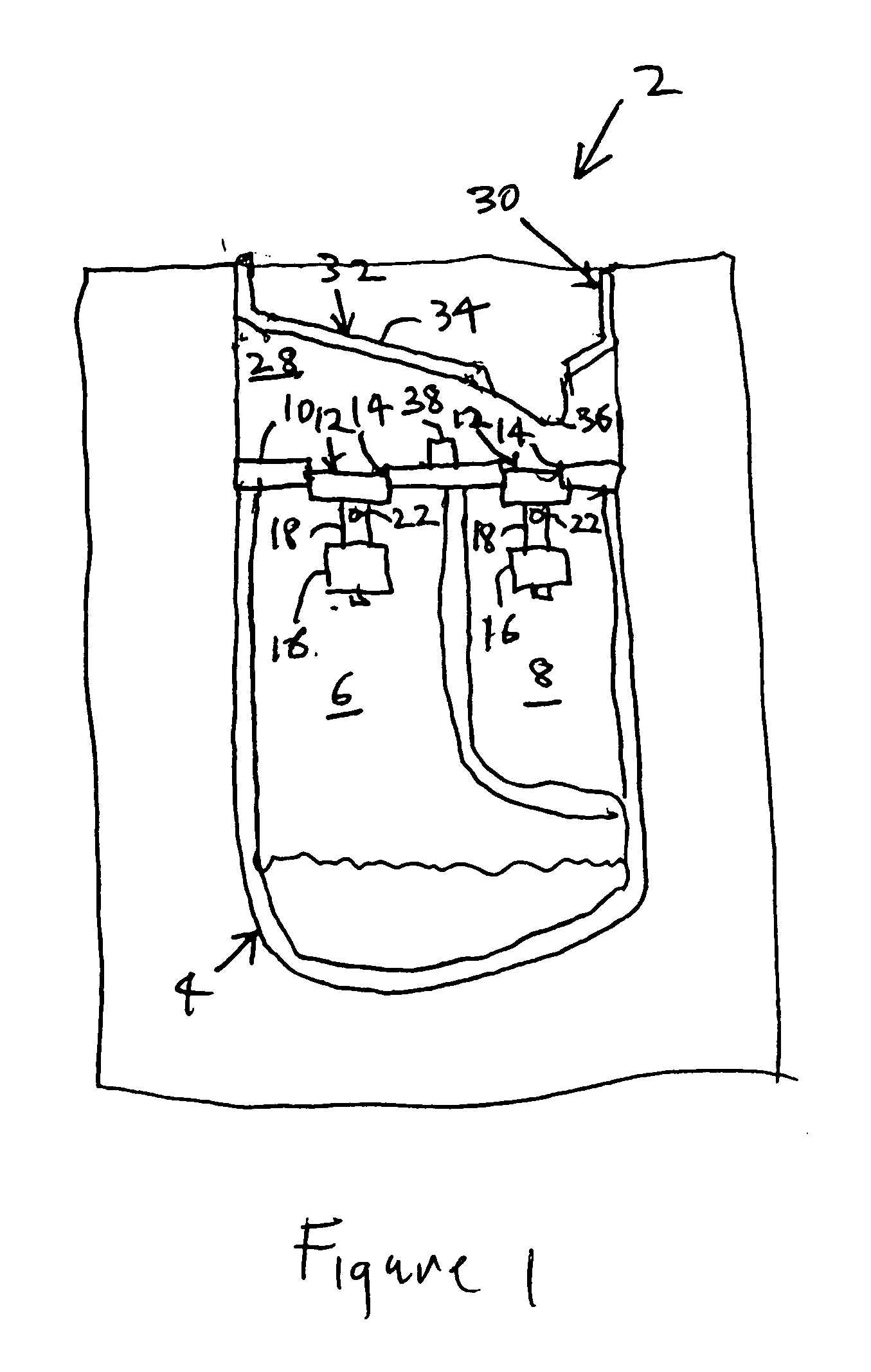
[0013] The primary oil tank 6 and the secondary oil tank 8 have a “full” level at the same height as controlled by a baffle plate 10 common to both the primary oil tank 6 and the secondary oil tank 8. A float valve 12 sits in the primary oil tank 6. Another float valve 12 sits in the secondary oil tank 8. Each float valve 12 mounts in a mating aperture 14 that passes throu...


PUM


Abstract

A twin lubrication oil tank filling system with a single oil fill port that prevents overfilling of both a primary oil tank and a secondary oil with a gravity fill system by directing oil primarily into the secondary oil tank by means of a special oil diverter, a float valve for the secondary oil tank that closes when the oil level in the secondary tank reaches a full level to cause additional oil flow to pour into the primary oil tank and a float valve for the primary oil tank that closes when the oil level in the primary tank reaches a full level.

Description

FIELD OF THE INVENTION [0001] The invention relates to lubrication systems for machinery, and more particularly to a twin lubrication oil tank filling system with a common lubrication oil fill port for machinery that requires two separate lubrication oil systems. BACKGROUND OF THE INVENTION [0002] A gearbox assembly to couple a prime mover to a load generally requires a lubrication system for lubricating its gears and bearings with lubrication oil. For example, an aeronautical auxiliary power unit (APU) has such a gearbox that connects a prime mover in the form of a gas turbine engine to loads such as a load compressor, electric generator and hydraulic pump. A lubrication oil tank generally mounts within the gearbox housing to provide a reservoir of such lubrication oil for the gearbox lubrication system. [0003] Loads coupled to the gearbox may have their own lubrication system. For instance, the generator connected to such a gearbox may require lubrication by means of a lubrication...

Claims


Application Information

Patent Timeline
Patent Type & Authority Applications(United States)
IPC IPC(8): F16N7/02
CPCF16N37/00F16N19/00Y10T137/469Y10T137/4824Y10T137/7433Y10T137/86212
Inventor ROLLINS, MICHAEL J.SHATZ, MARK N.BRILL, JEFFREY C.
Owner HAMILTON SUNDSTRAND CORP
Why Eureka
Try Eureka