Ceramic Heater, Method of Producing the Same, and Glow Plug Using a Ceramic Heater

a ceramic heater and ceramic heater technology, which is applied in the direction of ohmic-resistance heating, ohmic-resistance electrodes, light and heating apparatus, etc., can solve the problems of sheath heater durability problems, low thermal conductivity, and long time required for raising the temperatur

Inactive Publication Date: 2007-09-13
NGK SPARK PLUG CO LTD
View PDF3 Cites 21 Cited by
  • Summary
  • Abstract
  • Description
  • Claims
  • Application Information

AI Technical Summary

Benefits of technology

[0006] The invention has been conducted so as solve the above-discussed problems. It is an object of the invention to provide a ceramic heater in which a damage in a joining portion between a heating portion and a lead portion is suppressed and the reliability is excellent, a method of producing it, and a glow plug using it. MEANS FOR SOLVING THE PROBLEMS
[0026] In the method of producing of a ceramic heater of the invention, preferably, the ejector pins include: a first ejector pin which is closest to the unsintered heating portion among the ejector pins that are to butt against the unsintered lead portions; a second ejector pin which is to butt against the unsintered flat part that is adjacent to the first ejector pin; and a third ejector pin which butts against the unsintered lead portion that is adjacent to the first ejector pin, and an axial distance between the first ejector pin and the second ejector pin is shorter than an axial distance between the first ejector pin and the third ejector pin. According to the configuration, with respect to the unsintered heating portion having a small sectional area, the ejector pins can be placed with a reduced interval. When the unsintered resistor member is to be taken out from the molding die, the unsintered resistor member can be easily separated from the face of the molding die, and a phenomenon that the unsintered heating portion buckles or deforms, or that a crack occurs in a root part of the portion can be suppressed.

Problems solved by technology

In such a sheath heater, however, the thermal conductivity is low, and a long time is required for raising the temperature because the heating coil is embedded in the insulating powder.
For the requests, a sheath heater has a problem in durability because the heating coil is made a metal.

Method used


Image

  • Ceramic Heater, Method of Producing the Same, and Glow Plug Using a Ceramic Heater
  • Ceramic Heater, Method of Producing the Same, and Glow Plug Using a Ceramic Heater
  • Ceramic Heater, Method of Producing the Same, and Glow Plug Using a Ceramic Heater

Examples


example 1

[0076] First, samples of the unsintered resistor member 200 in which the projection 4 is disposed in the unsintered heating portion 231, and those in which the projection is not disposed were injection molded, and taken out from the molding dies. It was checked whether a defect such as a crack is caused in the unsintered heating portion 231 of each sample or not. Namely, samples of the unsintered resistor member 200 of the invention having the projection 4 in the unsintered heating portion 231 of the embodiment, and those of the unsintered resistor member 200 of a comparative example not having the projection 4 are produced. The samples of the invention were molded by the molding dies 51, 61 having the configuration in which, in the unsintered heating portion 231, the portion P7 of the projection 4 is pushed out by the ejector pin T7. The samples of the comparative example were molded by molding dies in which an ejector pin is not placed in a position corresponding to the above. Bot...

example 2

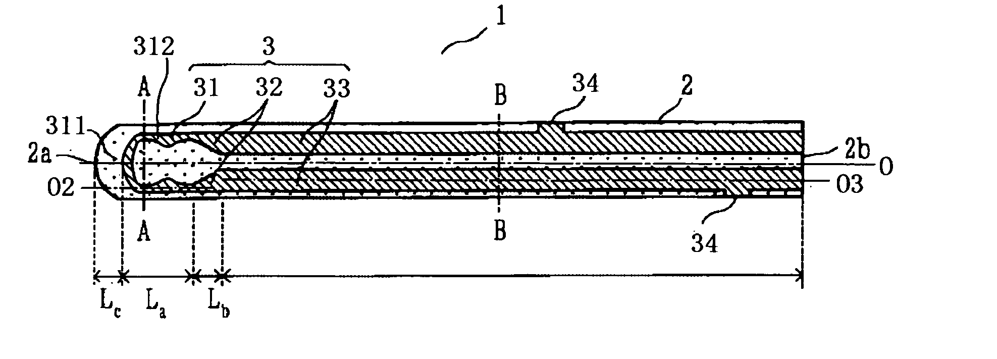
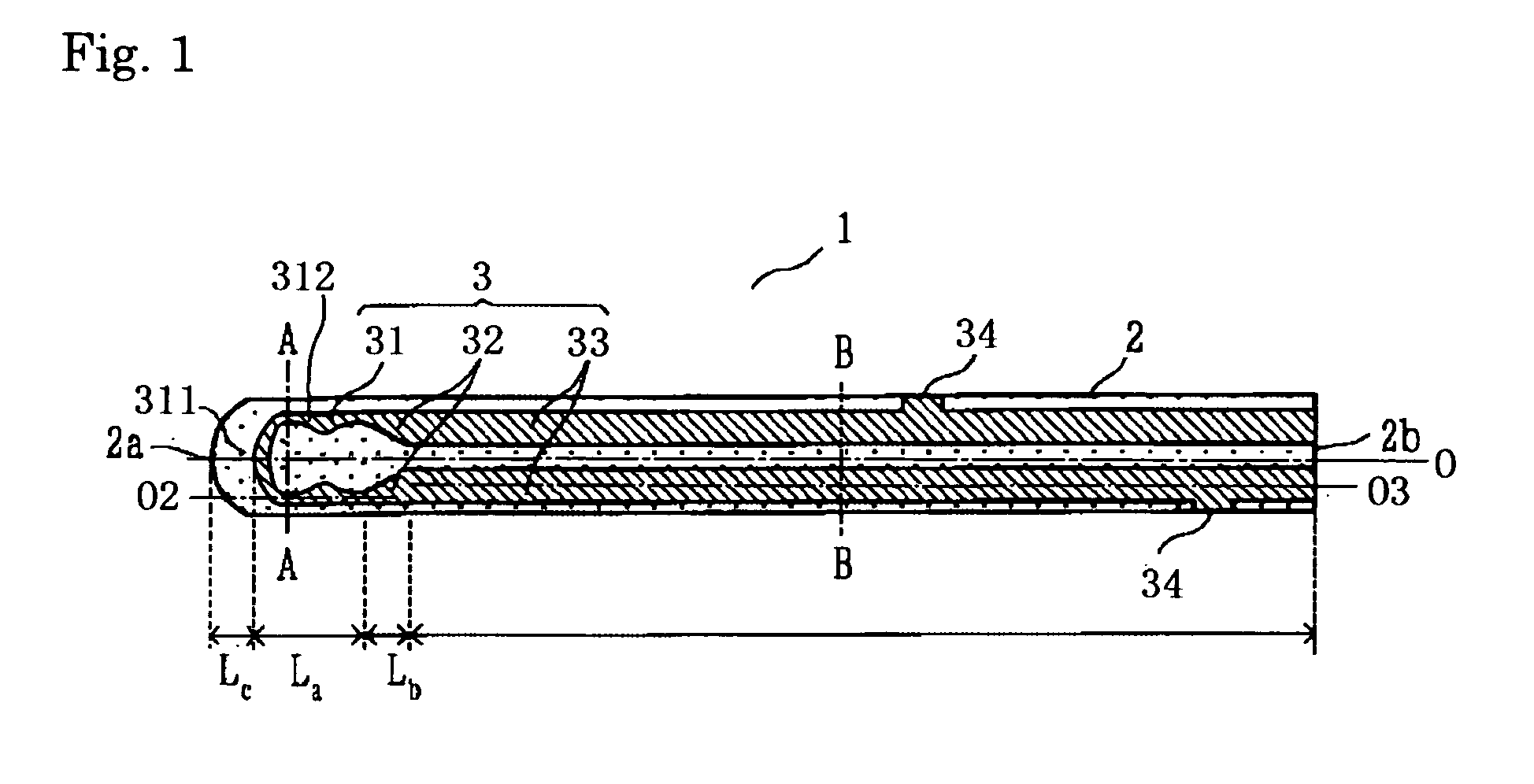
[0078] Next, the resistor member 3 made from a conductive ceramic and having the heating portion 31 and the pair of lead portions 33 which are continuously formed was embedded in the rod-shaped support 2 made from an insulative ceramic, to produce the ceramic heaters 1 of sample Nos. 1 to 6 which are configured as shown in FIG. 1. Using the ceramic heaters 1, glow plugs 20 for starting a diesel engine and having the configuration shown in FIG. 7 were produced.

[0079] The insulative ceramic constituting the support 2 was 96.5(0.89Si3N4-0.08Er2O3-0.01V2O5-0.02WO3)-3.5MoSi2 (weight ratio). The conductive ceramic constituting the resistor member 3 was 70WC / 30Si3N4-3.96Er2O3-1.61SiO2 (weight ratio).

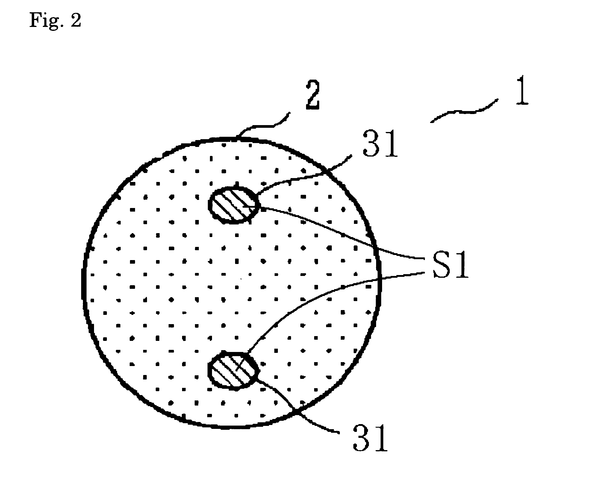
[0080] The section shapes in the longitudinal direction of the ceramic heaters 1 of sample Nos. 1 to 6 were three kinds of section shapes shown in FIGS. 8 to 10. Sample Nos. 1 and 5 had the shape shown in FIG. 8, sample Nos. 2 and 3 had the shape shown in FIG. 9, and sample Nos. 4 and 6 had t...

example 3

[0088] Next, in order to check influences on the resistance (R1) of the resistor member 3, ceramic heaters which are identical in material and shape with the ceramic heater 1 produced in sample No. 2 were produced while the resistance (R1) of the resistor member 3 was changed by changing the sintering temperature in the range of 1,700 to 1,800° C. At this time, the resistance (R1) of the resistor member 3 was 249 to 478 mΩ. Using the ceramic heaters 1, glow plugs 20 of sample No. 7 to 10 for starting a diesel engine were produced.

[0089] In the glow plugs 20, the power consumption when the glow plugs were heated to 1,250° C., the heating temperature per W, and the 1,000° C.-reaching time period at an application of 11 V were measured. The results are shown in Table 7.

TABLE 7Power1,000° C.-consumptionreaching timeinperiod atResistance ofheatHeatingapplicationSinteringresistorgenerationtemperatureoftemperaturememberof 1,250° C.per11 V(° C.)(mΩ)(W)W (° C. / W)(sec.)Sample71,70047850.52...


PUM


Abstract

A ceramic heater in which a damage in a joining portion between a heating portion and a lead portion is suppressed and the reliability is excellent is provided. In a ceramic heater (1) including: a rod-shaped support (2) which is made from an insulative ceramic; and a resistor member (3) including a heating portion (31) embedded in a tip end part of the support (2), and a pair of lead portions (33) which extend from the heating portion (31) toward a rear end side of the support (2), the heating portion (31) and the lead portions (33) are made from the same conductive ceramic.

Description

TECHNICAL FIELD [0001] The present invention relates to a ceramic heater, a method of producing the same, and a glow plug using the ceramic heater, and particularly to a ceramic heater which is suitable in a glow plug used for starting a diesel engine, a method of producing the same, and a glow plug using the same. BACKGROUND ART [0002] Conventionally, a sheath heater in which a heating coil embedded in insulating powder is placed in a bottomed cylindrical metal sheath is used for starting a diesel engine. In such a sheath heater, however, the thermal conductivity is low, and a long time is required for raising the temperature because the heating coil is embedded in the insulating powder. Recently, it is requested to raise the heating temperature of the heater to 1,000° C. or more, and the time period of afterglow in which the heater generates heats even after the engine is started tends to be prolonged. For the requests, a sheath heater has a problem in durability because the heati...

Claims


Application Information

Patent Timeline
Patent Type & Authority Applications(United States)
IPC IPC(8): F23Q7/22F23Q7/00H05B3/03H05B3/14H05B3/48
CPCF23Q7/001H05B2203/027H05B3/141F23Q2007/004
Inventor HOTTA, NOBUYUKIMATSUBARA, KATSURAYAMAMOTO, YOSHIHIROITO, MASAYA
Owner NGK SPARK PLUG CO LTD
Why Eureka
Try Eureka