INK jet recording head and ink jet recording apparatus

Inactive Publication Date: 2007-09-13
FUJIFILM CORP
View PDF3 Cites 27 Cited by
  • Summary
  • Abstract
  • Description
  • Claims
  • Application Information

AI Technical Summary

Benefits of technology

[0030]Further, according to a fourth aspect of the present invention, there is provided an ink jet recording apparatus, including: an ink jet head having a head substrate in which resin-made ink guides are formed, each ink guide for forming a meniscus of ink, and ejection electrodes, each for forming an electric field on a tip end of said ink guide and ejecting the ink as ink droplets by exerting an electrostatic force onto the ink, in which said ink guide is coated with a protective layer; and moving means for moving at least one of said ink jet head and said recording medium so that said recording medium can move relatively to said ink jet head, wherein an image corresponding to image data is recorded on the recording medium by means of the ink jet head.
[0031]In the ink jet head of the first aspect of the present invention, the ejection port for ejecting the ink droplet is formed in the ejection port substrate, and the surface of the ejection port substrate on the side from which the ink droplet is ejected is coated with the diamond like carbon layer. Accordingly, even in the case of repeating the maintenance such as the brushing for the ink ejection surface, the high ink repellency can be maintained for a long period of time. Therefor

Problems solved by technology

However, physical strength of the ink repellent layer as described above is weak, and there is a problem in that, for example, when maintenance is performed for the surface on the ink ejection side by rubbing the surface by means of a soft brush in order to prevent ink clogging of the nozzle, the resin-made ink repellent layer is peeled off, and the ink cannot be stably ejected from the ejection port.
However, since the ink guide is extremely minute, the brush may come in contact

Method used


Image

  • INK jet recording head and ink jet recording apparatus
  • INK jet recording head and ink jet recording apparatus
  • INK jet recording head and ink jet recording apparatus

Examples


Example

[0061]Hereinafter, an ink jet head and an ink jet recording apparatus of the present invention will be described in detail based on preferred embodiments illustrated in the accompanying drawings.

[0062]First, an ink jet head of the first aspect of the present invention and an ink jet recording apparatus of the second aspect of the present invention will be explained referring to FIGS. 1A to 9B.

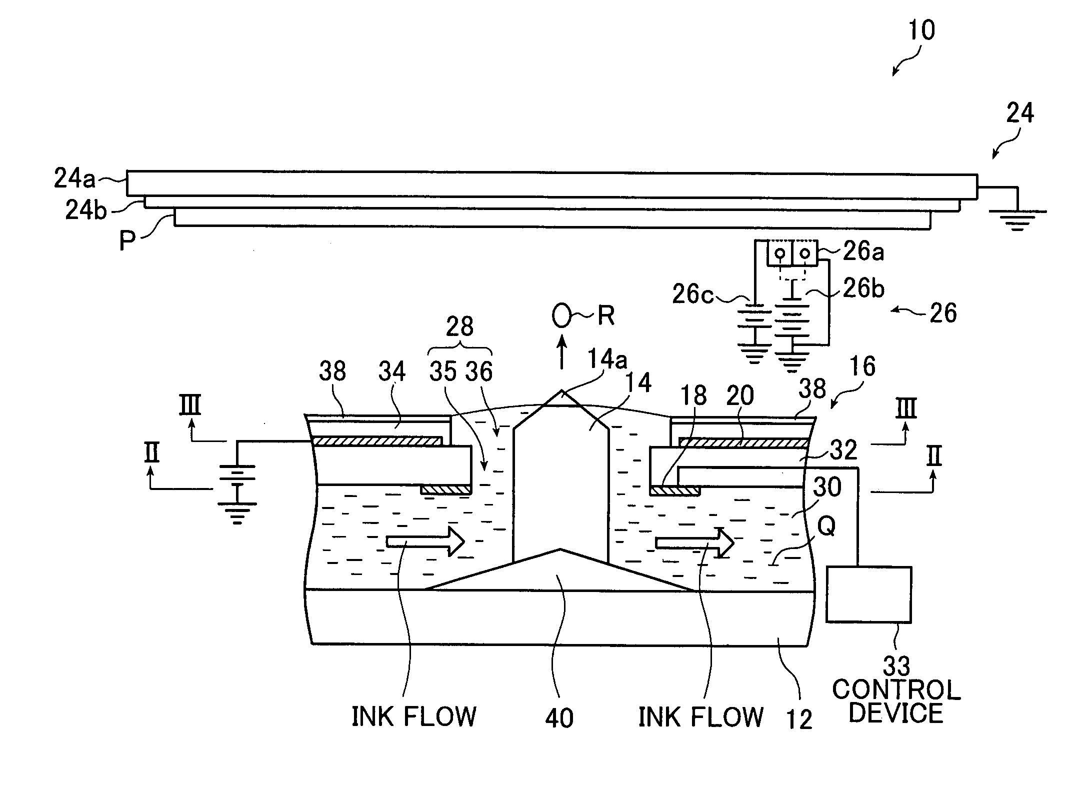
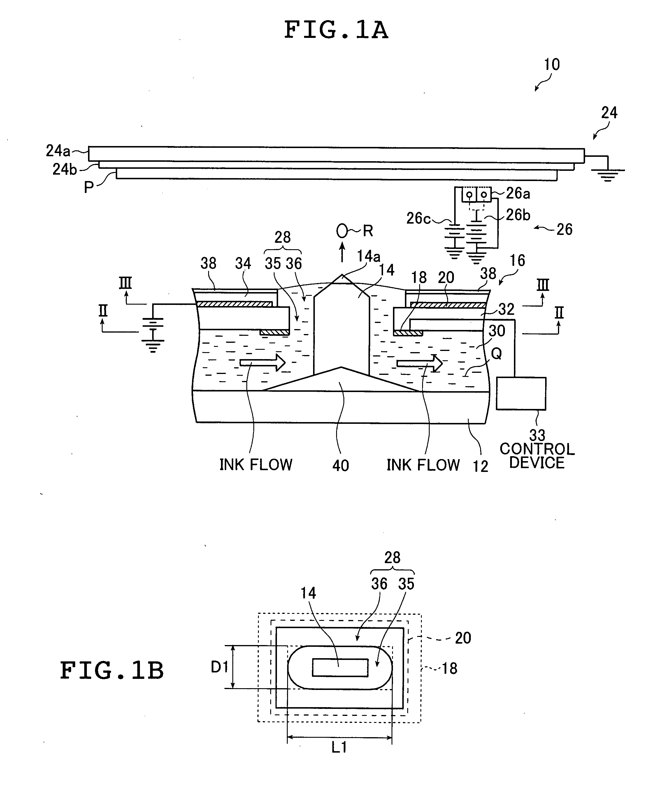
[0063]FIG. 1A schematically shows a cross section of an outlined configuration of the ink jet head according to the first aspect of the present invention, and FIG. 1B shows a top view of an ejection port substrate16 shown in FIG. 1A. As shown in FIG. 1A, an ink jet head 10 comprises a head substrate 12, ink guides 14, and the ejection port substrate 16 in which ejection ports 28 are formed. Ejection electrodes 18 are disposed on the ejection port substrate 16 so as to surround the respective ejection ports 28. At a position facing the surface of the ink jet head 10 on an ink ejection side (i.e....


PUM


Abstract

An ink jet head includes an ejecting unit for ejecting ink droplets toward a recording medium and an ejection port substrate in which ejection ports from which ink droplets are ejected are opened, in which a surface of the ejection port substrate on a side from which the ink droplets are ejected is coated with a diamond like carbon layer. Alternatively, the ink jet head includes a head substrate in which resin-made ink guides are formed, each ink guide for forming a meniscus of the ink and ejection electrodes, each for forming an electric field on a tip end of the ink guide and ejecting the ink as the ink droplets by exerting an electrostatic force onto the ink, in which the ink guide is coated with a protective layer such as the diamond like carbon layer. An ink jet recording apparatus includes the ink jet head and a moving unit for moving the ink jet head and the recording medium relatively.

Description

[0001]The entire contents of the document cited in this specification are herein incorporated by reference.BACKGROUND OF THE INVENTION[0002]The present invention relates to an ink jet head and an ink jet recording apparatus. Specifically, the present invention relates to an ink jet head for ejecting ink as ink droplets, and to an ink jet recording apparatus using the ink jet head, or the present invention relates to an electrostatic ink jet head for ejecting ink droplets by exerting an electrostatic force onto ink at a tip end of an ink guide, and to an ink jet recording apparatus using the electrostatic ink jet head.[0003]As an ink jet recording system in which ink is ejected as ink droplets, there are an electrostatic system in which ink droplets are ejected by exerting an electrostatic force onto the ink, an electrothermal conversion system in which ink droplets are ejected by pressure of steam generated by heat of a heating element, a piezoelectric system in which ink droplets a...

Claims


Application Information

Patent Timeline
IPC IPC(8): B41J2/135
CPCB41J2/1433B41J2/1606B41J2/162B41J2/1626B41J2/1646B41J2/1642B41J2/1643B41J2/1645B41J2/1631
Inventor FURUKAWA, KOJI
Owner FUJIFILM CORP
Why Eureka
Try Eureka