Optical information medium and recording method therefor

a technology of optical information and recording method, applied in the field of optical information medium, to achieve the effect of high density

Inactive Publication Date: 2004-04-27
TAIYO YUDEN KK
View PDF10 Cites 7 Cited by
  • Summary
  • Abstract
  • Description
  • Claims
  • Application Information

AI Technical Summary

Benefits of technology

Further, a full width at half maximum (FWHM) of the groove 3 on the transparent substrate 1 is selected from one-third (1 / 3) to a half (1 / 2) of the pitch p of the groove 3. The FWHM of the groove 3 means the width of the groove at the position where the depth Ds is a half (1 / 2) of the depth Ds of the groove 3 which is formed on the transparent substrate 1. When the NA of the objective lens (o) is set to be 0.65.+-.0.02 when recording, although previously mentioning that the beam spot of the recording laser beam can be made smaller, however, if the FWHM of the groove 3 is widened to exceed. a half (1 / 2) of the pitch p (0.74 .mu.m) of the groove 3, no effect can be obtained by focusing the recording laser beam to the beam spot. On the other hand, if the FWHM of the groove 3 is narrowed so as not to reach to one-third (1 / 3) of the groove 3, sufficient modulation amplitude cannot be obtained when reproducing by selecting the NA of the objective lens (o) to be approximately 0.60.+-.0.02.
According to the present invention, when recording signals onto the optical information medium to meet the high density recording, it is possible to perform recording while focusing the recording laser beam into a small region or spot, by means of the optical pickup having the objective lens (o) of the NA 0.65.+-.0.02 larger than the NA 0.60.+-.0.02 of the objective lens for reproducing, thereby enabling recording at a high density. Moreover, the drawbacks which are likely to occur accompanying the enlargement in the NA of the objective lens (o) in the optical pickup can be solved by selecting the inclination angle of both sides of the groove for tracking on the transparent substrate of the optical information medium, the ratio between the width and pitch of the groove, or the index for film thickness of land / groove of the recording layer, appropriately. With this, it is possible to obtain reproduced signals which satisfy the requirements determined for a high density optical information medium, such as the DVD standard, with ease.

Problems solved by technology

However, when the NA of the objective lens is large, the focus point is likely to shift due to the inclination of the disc to an optical axis of the objective lens caused by the curvature of the discs, therefore, there may easily occur a problem, such as deterioration in the deviation of pit-and-land length, accompanying with the worth in balance between or among the pits of various length, including long and short ones which are formed through the recording operation.

Method used


Image

  • Optical information medium and recording method therefor
  • Optical information medium and recording method therefor
  • Optical information medium and recording method therefor

Examples


example 1

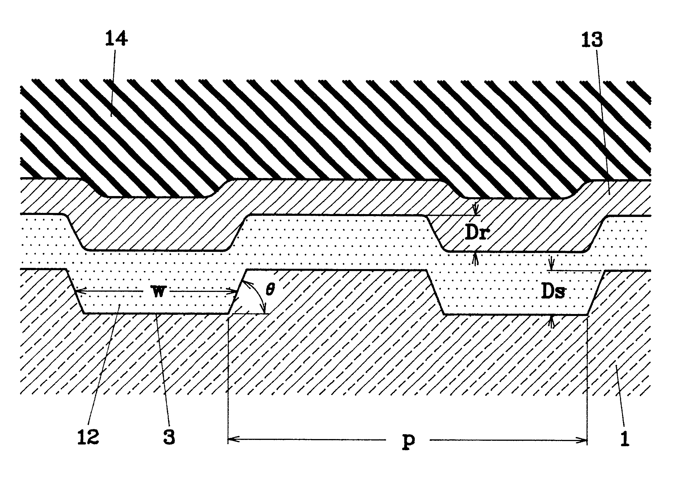
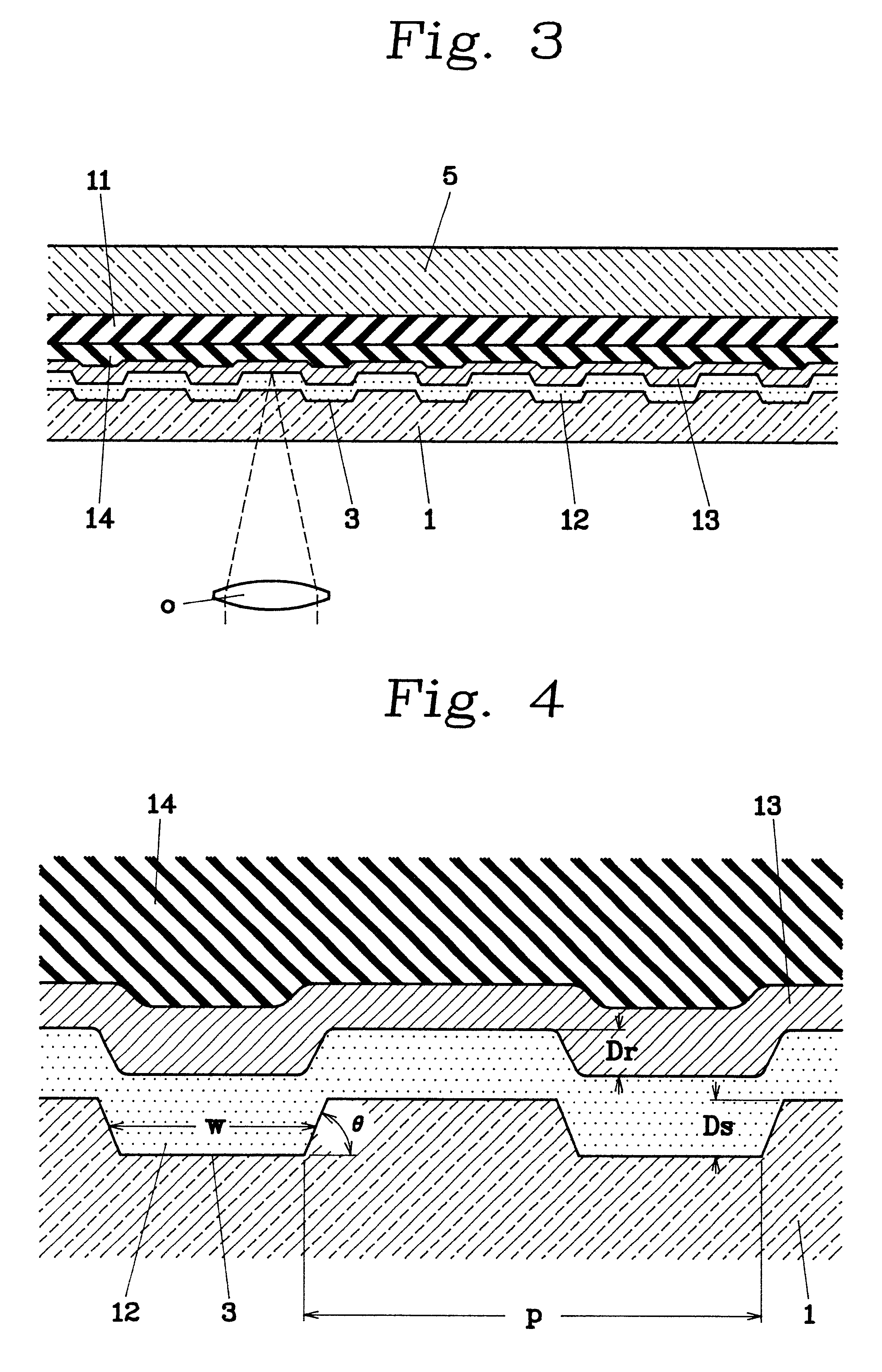
A transparent substrate 1 having a groove 3 for tracking on one side of the main surfaces, of 0.31 .mu.m in FWHM, 140 nm in depth, 65.degree. in inclination angle at both edges of groove, and 0.74 .mu.m in pitch, is prepared from a polycarbonate substrate of 120 mm.psi. in outer diameter, 15 mm.psi. in inner diameter, 0.597 mm in thickness, and 1.59 in refractive index.

On the side surface of the transparent substrate 1, having the groove 3 thereon, the recording layer 12 is formed by the spin coating film formation of a solution of cyanine dye (trimethylene dye).

The depth in position of the groove 3 mentioned above is 105 nm in the recording layer 12, and the index for film thickness of the land / groove of the recording layer is .varies.=1-Dr / Ds=0.25. Also, the FWHM of the groove 3 is 0.31.mu.m as mentioned in above, therefore, it is approximately 42% of the pitch of the groove 3, i.e., 0.74 .mu.m.

Further, Au is spattered onto the recording layer 12 so as to form the reflective layer...

example 2

The optical information medium is produced in the same manner to that of Example 1 mentioned above, but the groove 3 for tracking on the main surface of the transparent substrate 1 is determined to be 0.28 .mu.m in FWHM, 200 nm in depth, and 57.degree. in inclination angle at both edges of the groove thereof, everything else being the same as in Example 1 mentioned above.

The depth at the position of the groove 3 mentioned above is 135 nm in the recording layer 12, and the index for film thickness of the land / groove of the recording layer is .varies.=1-Dr / Ds 0.33. Also, the FWHM of the groove 3 is 0.28 .mu.m as mentioned above, therefore, it is approximately 39% of the pitch of the groove 3, i.e., 0.74 .mu.m.

On the optical information medium produced in this manner, an EFM-Plus signal is recorded at a recording power of 12 mW and wavelength of 655 nm, by using an optical pickup having the objective lens (o) of NA 0.66, in the same manner as Example 1 mentioned above. After being reco...

example 3

The optical information medium is produced in the same manner as in Example 1 mentioned above, but the groove 3 for tracking on the main surface of the transparent substrate 1 is determined to be 0.35 .mu.m in FWHM, 200 nm in depth, and 72.degree. in inclination angle at both edges of the groove, everything else being the same as in Example 1 mentioned above.

The depth at the position of the groove 3 mentioned above is 125 nm in the recording layer 12, and the index for the film thickness of the land / groove of the recording layer is .varies.=1-Dr / Ds =0.38. Also, the FWHM of the groove 3 is 0.35 .mu.m as mentioned above, therefore, it is approximately 47% of the pitch of the groove 3, i.e., 0.74 .mu.m.

On the optical information medium produced in this manner, an EFM-Plus signal is recorded at a recording power of 10 mW and wavelength of 635 nm, by using an optical pickup having the objective lens (o) of NA 0.64, in the same manner as Example 1. After being recorded thereon, the signal...


PUM

PropertyMeasurementUnit
wavelengthaaaaaaaaaa
thicknessaaaaaaaaaa
wavelengthaaaaaaaaaa

Abstract

An optical information medium made up of a transparent substrate capable of allowing a recording laser beam to penetrate therethrough; a recording layer formed on the transparent substrate; and a reflective layer formed on the recording layer and reflecting a reproducing laser beam thereupon. A numerical aperture of an objective lens of an optical pickup for irradiating the recording laser beam on the recording layer is approximately 0.65, and the numerical aperture of an objective lens of the optical pickup for irradiating the recording laser beam on the reflection layer is approximately 0.60. An inclination angle .theta. at both edges of the groove for tracking, being formed spirally on the surface of the transparent substrate on which the recording layer is formed, with respect to the main surface of the transparent substrate, is selected to be from 55.degree. to 75.degree.. An index .varies., expressed by 1-Dr/Ds when assuming that the depth of the groove on the transparent substrate is Ds and the depth of the recording layer at the position of said groove is Dr, is selected to be from 0.2 to 0.4. Further, the full width at half maximum of the groove on the transparent substrate is selected to be from one-third (1/3) to a half (1/2) of the pitch p of the groove. With this optical information medium, it is possible to record high density signals as signals that are readable optically, as well as to record them with stability.

Description

BACKGROUND OF THE INVENTION1. Field of the InventionThe present invention relates to an optical information medium, on which can be recorded information which is optically reproducible, and a recording method for recording signals that are optically readable, and in particular relates to the optical information medium and the recording method, for realizing a recording / reproducing system suitable for a high density recording medium on which the information can be recorded and reproduced with red color laser beam of a short wavelength of from 630 nm to 670 nm.2. Description of Related ArtWith the recent advances in development and application of a short wavelength laser, standardization has proceeded on a standard for DVDs (Digital Versatile Discs) which enables recording and reproducing at a high density, as well as the practical application thereof. The DVD has a data area at least provided on one surface of the substrate thereof, so as to form so-called pits as a means for informa...

Claims


Application Information

Patent Timeline
Patent Type & Authority Patents(United States)
IPC IPC(8): G11B7/007G11B7/24G11B7/00G11B7/004
CPCG11B7/24076G11B7/24079
Inventor FUJII, TORUTAJIMA, TOSHIAKITOMIZAWA, YUJINEGISHI, RYOUHAMADA, EMIKO
Owner TAIYO YUDEN KK
Why Eureka
Try Eureka