Optical Connector

a technology of optical fibers and connectors, applied in the field of optical connectors, can solve the problems of lack of alignment of the central axes z of parallel beams, the need for large-scale manufacturing apparatus such as a cob>2 /sub>laser and arc discharge apparatus, and the inability to position the optical fiber 320

Inactive Publication Date: 2007-09-13
TYCO ELECTRONICS JAPAN GK
View PDF6 Cites 29 Cited by
  • Summary
  • Abstract
  • Description
  • Claims
  • Application Information

AI Technical Summary

Problems solved by technology

When an eccentricity 6 is generated between the central axis Z of the parallel beam and the central axis A of the partially spherical lens 102, in cases where mutually facing optical fiber collimators are aligned with reference to the external diameter, a lack of alignment of the central axes Z of the parallel beams becomes a problem.
Therefore, there is a problem in that the central axes Z of the parallel beams may not coincide in cases where mutually facing optical fiber collimat

Method used


Image

  • Optical Connector
  • Optical Connector
  • Optical Connector

Examples


Embodiment Construction

)

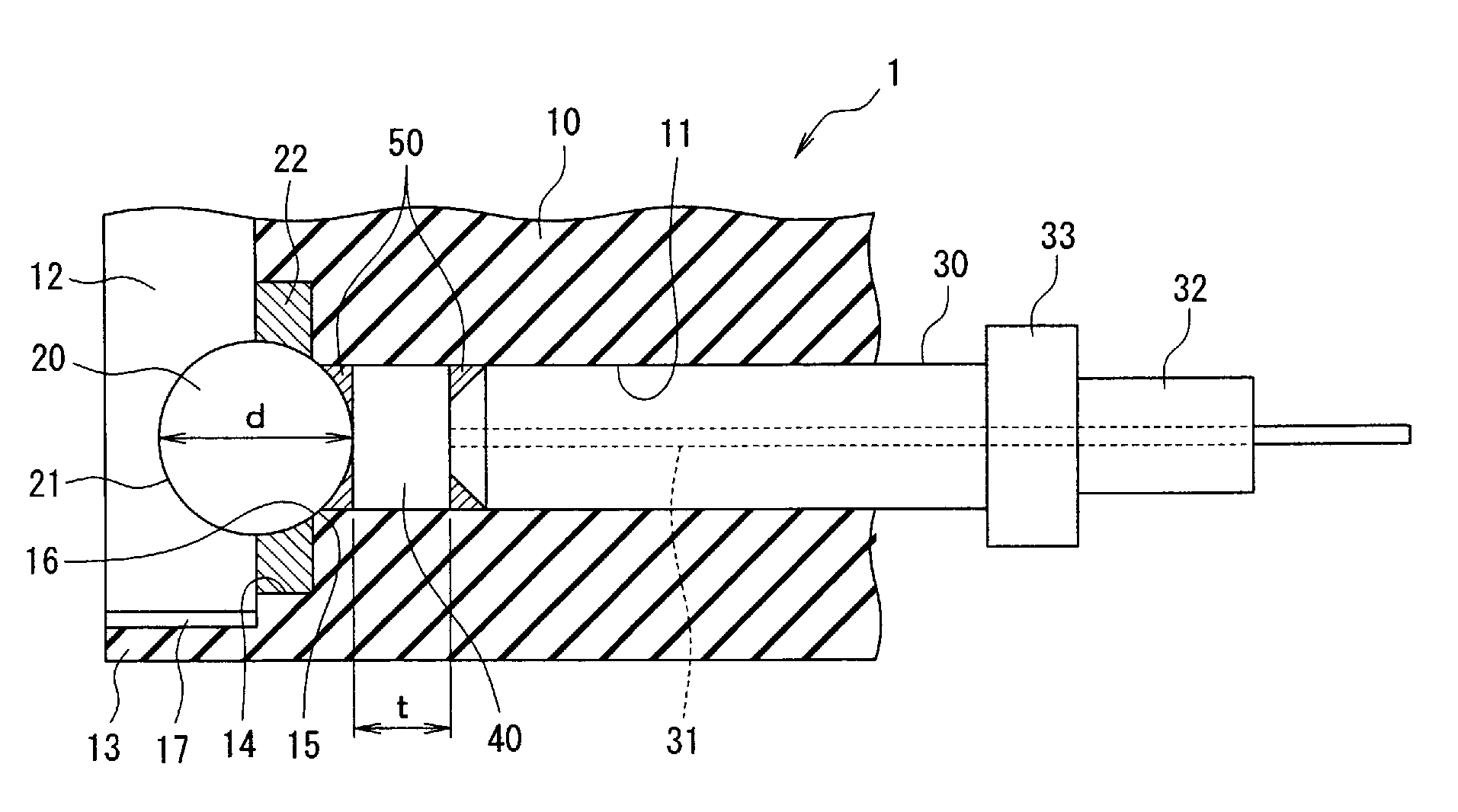
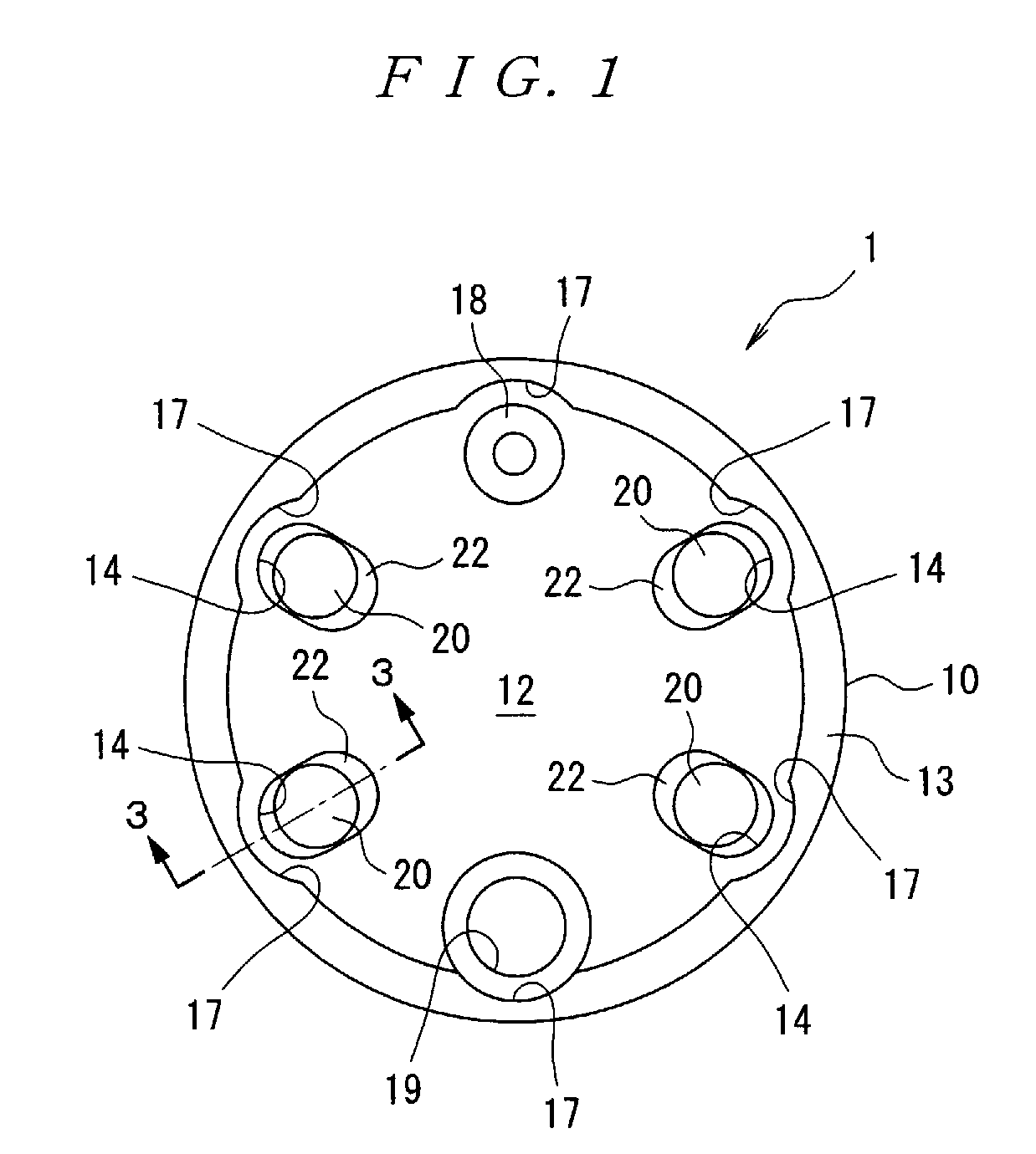
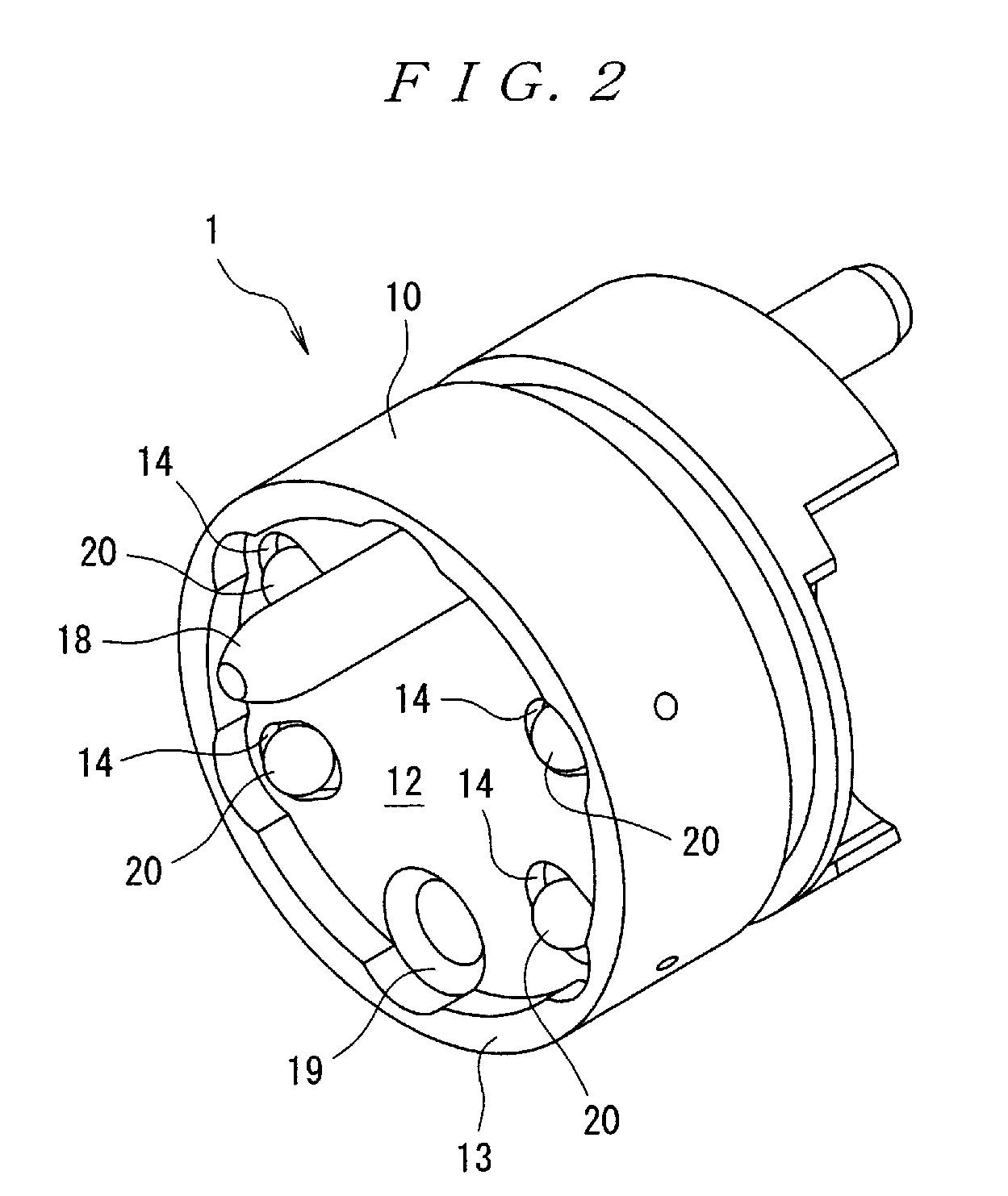
[0032]Next, embodiments of the present invention will be described with reference to the figures. In FIGS. 1 through 3, the optical connector 1 comprises a housing 10, a plurality of spherical lenses 20 (four lenses in the present embodiment), and a plurality of ferrules 30 (four ferrules in the present embodiment) that respectively incorporate optical fibers 31.

[0033]Here, the housing 10 is formed in a cylindrical shape as shown in FIGS. 1 and 2, and a circular recessed section 12 for mating with a mating optical connector (connector having the same shape as the optical connector 1) is formed in the front end portion (left end portion in FIGS. 2 and 3) of this housing. A cylindrical outer wall 13 that surrounds the recessed section 12 is provided on the outside of the recessed section 12. The housing 10 is manufactured from a resin into which a glass filler is mixed, but this housing may also be manufactured from a metal such as stainless steel. Furthermore, a plurality of ferrule...


PUM


Abstract

The optical fiber connector of the present invention includes a housing having a ferrule receiving passageway and a lens receiving portion which is disposed on the front end portion of this ferrule receiving passageway. A central axis is coaxial with the central axis of the ferrule receiving passageway. A spherical lens is fastened to the lens receiving portion and a ferrule is inserted into the ferrule receiving passageway from the rear side and is incorporated with an optical fiber whose front end surface is perpendicular to the central axis. A transparent block having a refractive index that is substantially the same as the refractive indices of the lens and optical fiber is disposed between the lens and the ferrule so that this block contacts the lens, the ferrule, and the optical fiber. A refractive index matching agent having a refractive index substantially the same as the refractive indices of the lens and optical fiber is applied around the contact point between the lens and the block and around the contact surface between the ferrule and the block. The thickness of the block in the direction of beam transmission is set to be the same as the distance to the focal point from the end surface of the lens.

Description

CROSS-REFERENCE TO RELATED APPLICATIONS[0001]This application claims the benefit of the filing date under 35 U.S.C. §119(a)-(d) of Japanese Patent Application No. 2006-66182, filed Mar. 10, 2006.FIELD OF THE INVENTION[0002]The present invention relates to an optical connector comprising an optical element such as an optical fiber collimator.BACKGROUND[0003]When high-speed large-capacity optical fiber communication systems are built, numerous optical devices are used. Such devices include devices that extract an optical signal of an arbitrary wavelength from an optical signal obtained by multiplexing a plurality of wavelengths, devices that use an optical crystal for matching the phase of the optical signal, and the like, and numerous optical fiber collimators which convert an optical signal emitted and spread from an optical fiber into parallel beams or which cause parallel beams to collect in an optical fiber.[0004]The main function of such optical fiber collimators is to propagate...

Claims


Application Information

Patent Timeline
IPC IPC(8): G02B6/32
CPCG02B6/32G02B6/3883G02B6/3878
Inventor KOBAYASHI, SHIGERUOHTSU, NOBUAKIHAYASHI, TAKEHIRO
Owner TYCO ELECTRONICS JAPAN GK
Why Eureka
Try Eureka