
Image forming apparatus

a technology of forming apparatus and cleaning blade, which is applied in the direction of electrographic process apparatus, instruments, optics, etc., can solve the problems of short life of cleaning blade, abrasion of cleaning blade edge, so as to reduce the abrasion of cleaning blade, less shifted, and greater difference of circumferential speed

Active Publication Date: 2007-09-13
KONICA MINOLTA BUSINESS TECH INC
View PDF5 Cites 4 Cited by
  • Summary
  • Abstract
  • Description
  • Claims
  • Application Information

AI Technical Summary

Benefits of technology

[0023]In order to address the drawback of the abrasion of the cleaning blade for the image carrier, the present inventors have found it effective to prevent the cohesive mass generated on the intermediate transfer member from being shifted onto the image carrier. More importantly, the inventors have revealed that the cohesive mass is less shifted from the intermediate transfer member onto the image carrier, as there is greater difference of the circumferential speeds between the image carrier and the intermediate transfer member. circumferential speed of the image carrier is usually set to be slightly offset from that of the intermediate transfer member so as to prevent the out-of-color-registration. However, the present inventors have confirmed that the difference of the circumferential speeds for preventing the out-of-color-registration, which is disclosed in Reference 1, is too small to reduce the abrasion of the cleaning blade. Rather, in the image forming apparatus of Reference 1 that is designed to have substantially no difference of the circumferential speeds especially in the monochrome mode, the abrasion of the image-carrier cleaning blade is inevitable and may be accelerated.
[0024]Therefore, one of the purposes of the present invention is to provide an image forming apparatus which prevents the out-of-color-registration on the reproduced image and also reduces the abrasion of the image-carrier cleaning blade.

Problems solved by technology

Also, a cleaning blade of the image carrier, which removes the toner remained thereon even after primarily transferring the toner image, may have a short lifetime by readily wearing away during limited operation.
The cohesive mass passing through a gap between the cleaning blade and the intermediate transfer member causes the abrasion of the edge of the cleaning blade, and may chip off a portion of the edge of the cleaning blade.
The chipped portion of the edge causes the redundant toner on the image carrier that should have been removed off by the cleaning blade, to remain on the image carrier so that the toner image has an undesired line, which requires the cleaning blade to be replaced with a new one.
In the meanwhile, the abrasion of the image-carrier cleaning blade is likely accelerated when the developing device is not operated (i.e., no toner is supplied onto the image carrier).
However, when the image carrier continues to rotate without being supplied with toner from the developing device (i.e., no operation of the developing device), the stable layer shrinks and disappears due to no supply of the toner or the external additive of the toner.
In general, the toner in the developing device is exposed to mechanical and electrical stress in a supply and / or restriction step and may be deteriorated for a long-term operation of the developing device.
The toner deterioration causes various problems appeared on the reproduced image such as a fogged toner, a spilled toner, a reduced density of image, and an uneven density of image.
Therefore, the image-carrier cleaning blade in the monochrome mode is more likely worn away than in the color mode.
Similarly, as the image forming apparatus with the tandem engine is used in the monochrome mode, since three of imaging units except black one are not driven when forming the black image, the image-carrier cleaning blade of those imaging units are likely bladed away due to lack of the stable layer on the cleaning blade edge.

Method used


Image

  • Image forming apparatus
  • Image forming apparatus
  • Image forming apparatus

Examples


first embodiment

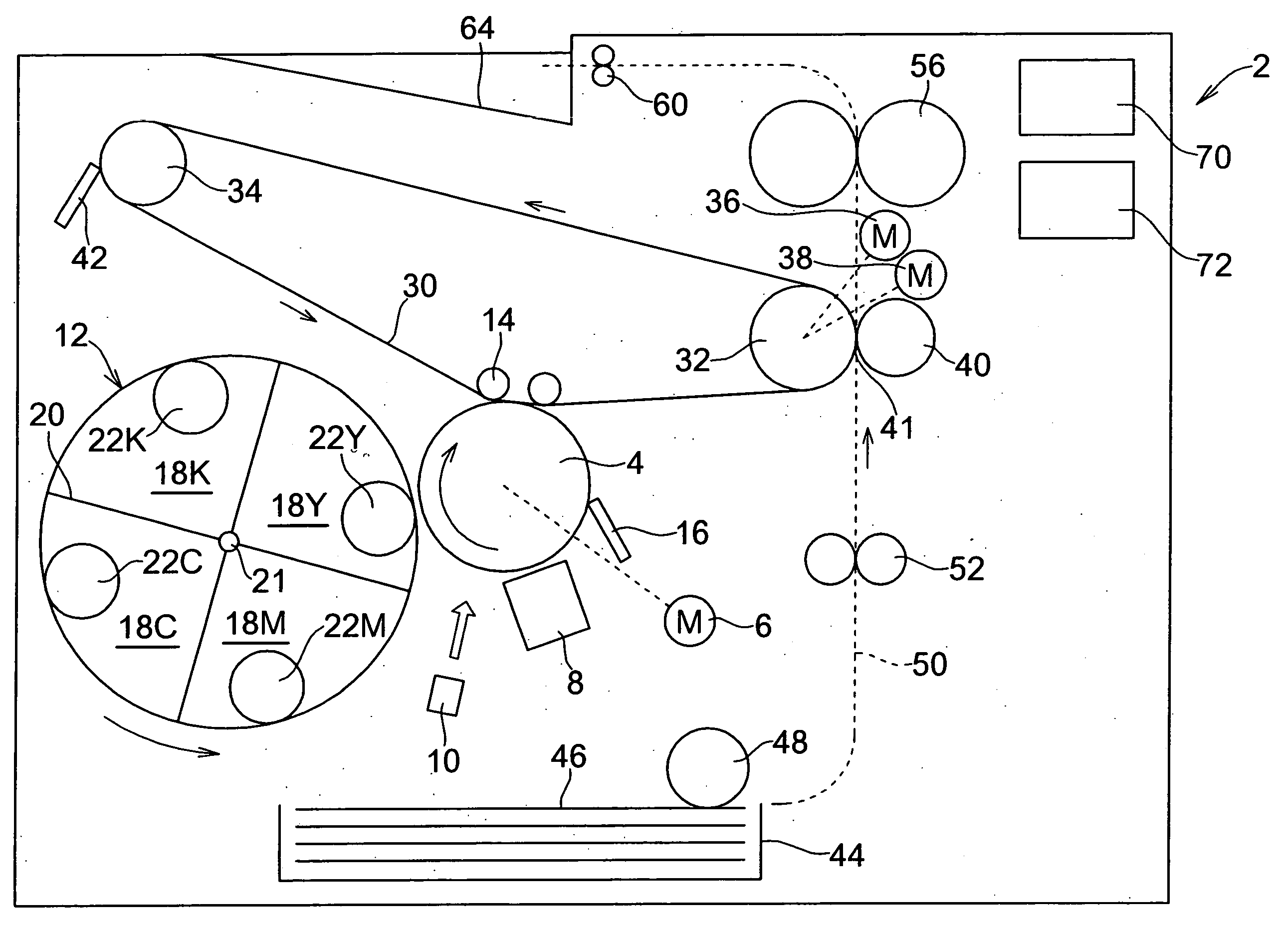
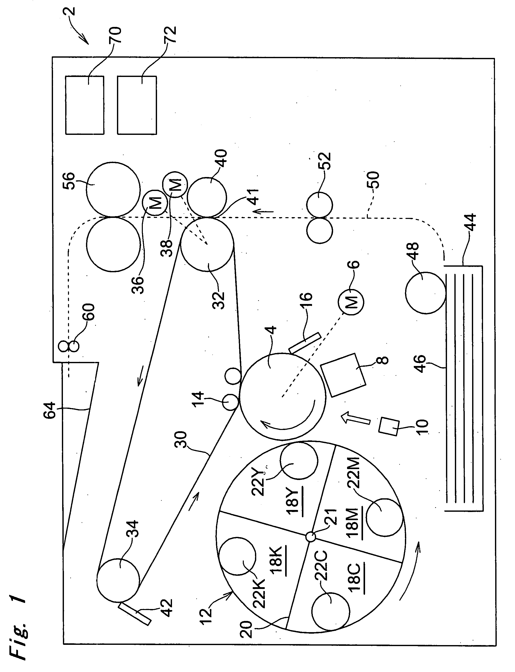
[0042]FIG. 1 is a schematic view of an image forming apparatus 2 with a four-cycle engine according to the first embodiment of the present invention. The image forming apparatus 2 includes a photoreceptor 4 as an image carrier appeared in the middle thereof. The photoreceptor 4 is driven by a driving motor 6 to rotate in a clockwise direction as illustrated by the arrow in FIG. 1 at a predetermined circumferential speed of VA.

[0043]Also, the image forming apparatus 2 includes, in general, several components provided around the photoreceptor 4 in a sequence of the clockwise direction, i.e., an electron charger 8, an exposing device 10, a developing device 12, a primary transfer roller 14, and a cleaning blade 16 for the photoreceptor (photoreceptor cleaning blade) 4. The electron charger 8 may be a scorotron charger in FIG. 1, for evenly charging the surface of the photoreceptor 4. The exposing device 10 forms an electrostatic latent image of each of the colors on the photoreceptor 4...

second embodiment

[0090]FIG. 4 is a schematic view of an image forming apparatus 102 with a tandem engine according to the second embodiment of the present invention. The image forming apparatus 102 includes an intermediate transfer belt 130 as the intermediate transfer member in the middle thereof.

[0091]The image forming apparatus 102 includes a switching device 170 for switching either one of the color mode where four-colored toner images are superimposed on the intermediate transfer belt 130 for forming the multi-color image, and the monochrome mode where only the black toner image is transferred on the intermediate transfer belt 130 for forming the monochrome image.

[0092]Also, the image forming apparatus 102 includes a controller 172 for driving the intermediate transfer belt 130 to rotate at a first circumferential speed in the color mode and at a second circumferential speed in the monochrome mode.

[0093]The intermediate transfer belt 130 is supported by outer surfaces of a pair of rollers 132, ...


PUM


Abstract

One of aspects of the present invention is to provide an image forming apparatus includes an intermediate transfer member rotating at a first circumferential speed, and an image carrier capable of having a plurality of toner images formed thereon in turn, each of the toner images having a color different from one another, for transferring the toner images onto the intermediate transfer member, the image carrier rotating at a second circumferential speed. At least one of the first and second circumferential speeds are adjustable in accordance with a driving mode selected from a group consisting of a monochrome mode and a color mode. Also, a first difference between the first and second circumferential speeds in the monochrome mode is greater than a second difference between the first and second circumferential speeds in the color mode.

Description

CROSS-REFERENCE TO RELATED APPLICATION[0001]The present application is based upon a Japanese Patent Application No. 2006-067409 filed on Mar. 13, 2006, all of which disclosure is incorporated by reference into the present application.BACKGROUND OF THE INVENTION[0002]1) Technical Field of the Invention[0003]The present invention relates to a complex type of an image forming apparatus performing various functions as a printer, a copier, and a facsimile machine, and in particular, relates to the image forming apparatus capable of switching a color mode for reproducing a color image and a monochrome mode for forming a monochrome image.[0004]2) Description of Related Arts[0005]In general, a color image forming apparatus has the color mode for forming the color image and the monochrome mode for reproducing the monochrome (black and white) image, which can be switched. Also, the color image forming apparatus is well known to have two types of driving engines such as a four-cycle engine and...

Claims


Application Information

Patent Timeline
Patent Type & Authority Applications(United States)
IPC IPC(8): G03G15/01
CPCG03G2215/0177G03G15/5008
Inventor YOSHIYAMA, TSUGIHITONAKANO, MUNENORI
Owner KONICA MINOLTA BUSINESS TECH INC
Learn More