Automatic transmission control system

a control system and automatic transmission technology, applied in the direction of gearing control, gearing elements, gearing, etc., can solve the problems of increasing the cost of manufacturing the automatic transmission, inconvenience in the freedom of the layout of the automatic transmission and the performance of the automatic transmission, etc., to increase the capacity of one frictional engaging element, increase the cost of manufacturing, and increase the effect of the capacity

Active Publication Date: 2007-09-13
JATCO LTD +1
View PDF3 Cites 10 Cited by
  • Summary
  • Abstract
  • Description
  • Claims
  • Application Information

AI Technical Summary

Benefits of technology

[0010] It has been discovered that raising the capacity of one frictional engaging element than required will lead to increased cost in manufacturing the automatic transmission. Also by increasing the capacity of one frictional engaging element may cause inconveniences in the freedom of the layout of the automatic transmission as well as performance of the automatic transmission.

Problems solved by technology

It has been discovered that raising the capacity of one frictional engaging element than required will lead to increased cost in manufacturing the automatic transmission.
Also by increasing the capacity of one frictional engaging element may cause inconveniences in the freedom of the layout of the automatic transmission as well as performance of the automatic transmission.

Method used


Image

  • Automatic transmission control system
  • Automatic transmission control system
  • Automatic transmission control system

Examples


second embodiment

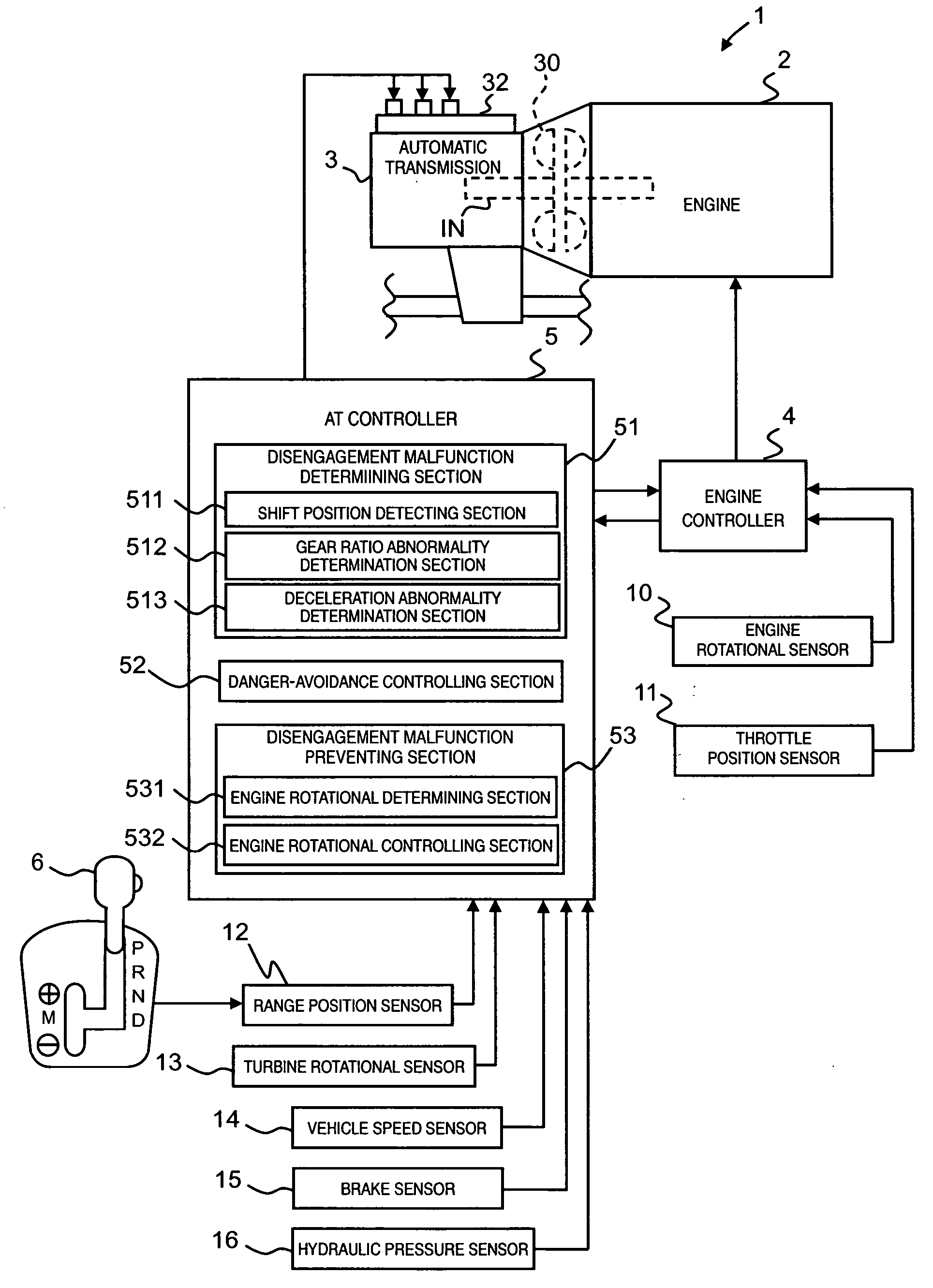
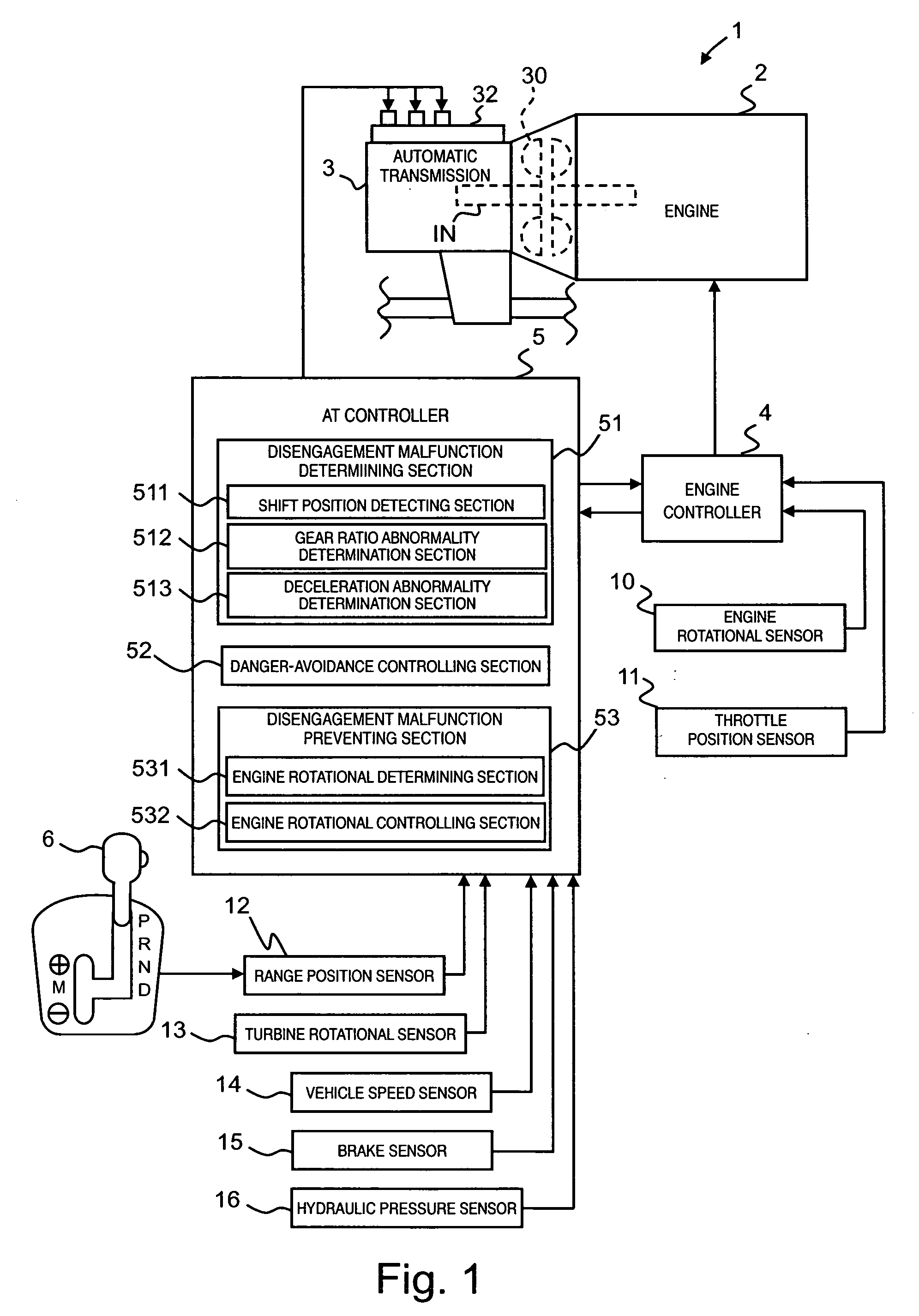
[0128] The constitution of the second embodiment of a control system for an automatic transmission is the same as that of the first embodiment.

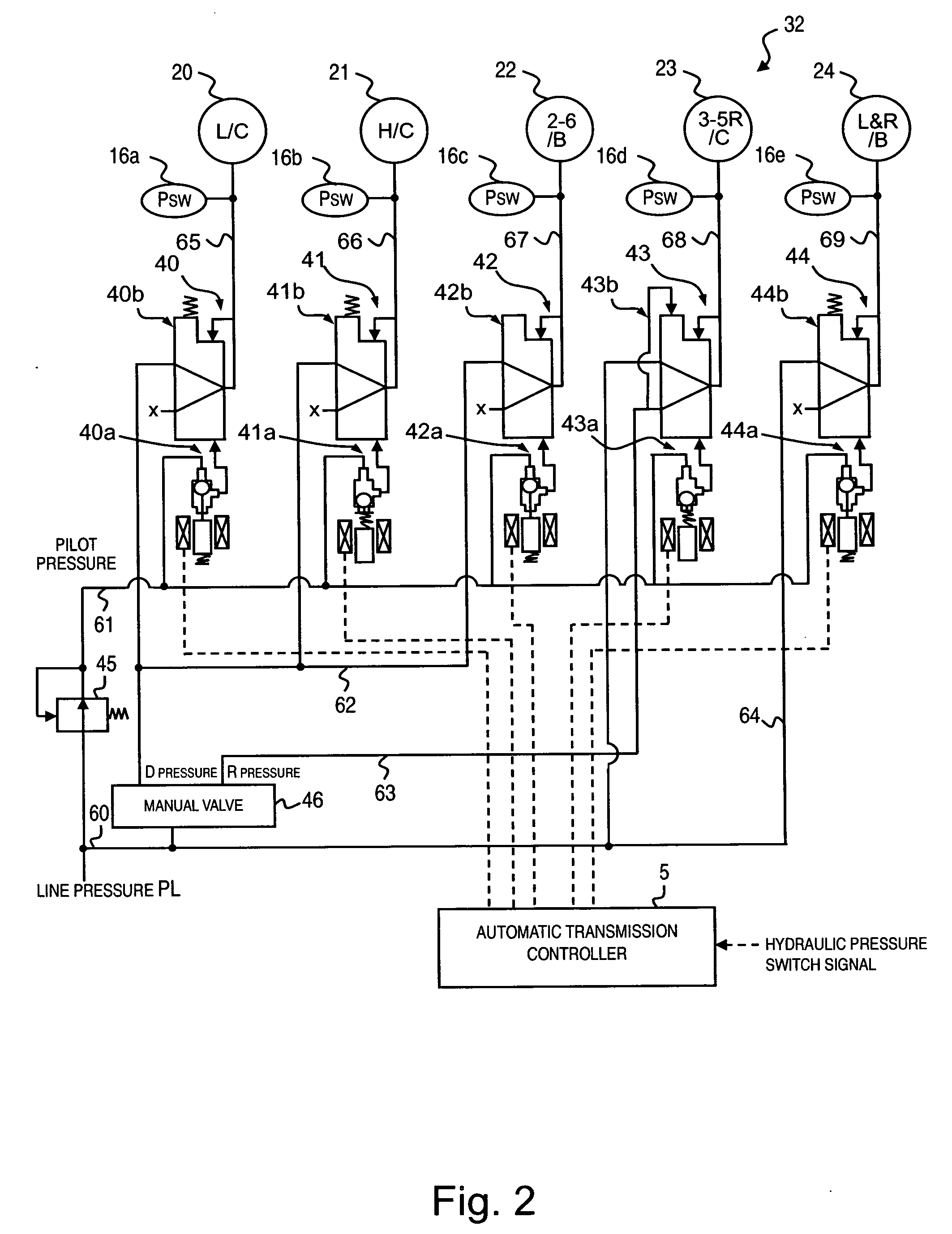
[0129] The second embodiment of a control system is different from the first embodiment in that it detects disengagement malfunction of a low clutch L / C (not a high clutch) as the first frictional engaging element, and performs control processing to prevent disengagement malfunction of a 3-5 reverse clutch 3-5 / C (not a 2-6 brake 2-6 / B) as the second frictional engaging element. In addition, a disengagement malfunction determining section 51 according to the second embodiment determines whether or not disengagement malfunction of the low clutch L / C occurs based mainly on a hydraulic pressure switch signal as different from the first embodiment. The other actions of the second embodiment are the same as those of the first embodiment.

[0130] As readily seen from FIG. 3, when the low clutch L / C has disengagement malfunction and P range or N rang...


PUM


Abstract

An automatic transmission control system is provided with a disengagement malfunction determining section and a disengagement malfunction preventing section in an automatic transmission in which the frictional engaging elements are selectively engaged and disengaged to change a rotational speed of a main power source. The disengagement malfunction determining section determines a disengagement malfunction with a first frictional engaging element from among a plurality of frictional engaging elements of the automatic transmission. The disengagement malfunction preventing section prevents disengagement malfunction of a second frictional engaging element from among the frictional engaging elements of the automatic transmission by lowering the rotational speed of the main power source to a level which will prevent the disengagement malfunction in the second frictional engaging element, when the disengagement malfunction determining section determines that the disengagement malfunction of the first frictional engaging element exist while the automatic transmission is in non-running range.

Description

CROSS-REFERENCE TO RELATED APPLICATIONS [0001] This application claims priority to Japanese Patent Application No. 2006-092804, filed on Jan. 26, 2006. The entire disclosure of Japanese Patent Application No. 2006-092804 is hereby incorporated herein by reference. BACKGROUND OF THE INVENTION [0002] 1. Field of the Invention [0003] The present invention generally relates to a control system for an automatic transmission. More specifically, the present invention relates to an automatic transmission control system for preventing disengagement malfunction of a frictional engaging element. [0004] 2. Background Information [0005] In a geared automatic transmission in which each of gear ratios is achieved by selectively engaging and releasing a plurality of clutches and brakes (each generically referred to as a “frictional engaging element”) a disengagement malfunction of one (first) frictional engaging element (for example, it is adhered) may cause a secondary malfunction of a disengageme...

Claims


Application Information

Patent Timeline
Patent Type & Authority Applications(United States)
IPC IPC(8): F16H31/00B60W10/04B60W10/06B60W10/10B60W10/11B60W10/115F02D29/00F16H59/08F16H59/42F16H59/68F16H61/12F16H61/68F16H61/684F16H61/686F16H63/50
CPCF16H61/12F16H2061/122F16H2061/1232Y10T477/675F16H2059/706Y10S477/906F16H2061/1276F16H61/00
Inventor TASAKA, HAJIMENAGASHIMA, FUMITAKAMICHIOKA, HIROFUMI
Owner JATCO LTD
Why Eureka
Try Eureka