
Closed loop control system for a high frequency oscillation ventilator

Active Publication Date: 2007-09-20
VYAIRE MEDICAL 211 INC
View PDF30 Cites 72 Cited by
  • Summary
  • Abstract
  • Description
  • Claims
  • Application Information

AI Technical Summary

Benefits of technology

[0025] The resulting MAP loop error signal is then filtered through an integral controller to generate an exhalation valve command signal for driving a valve actuator. Ideally, the valve actuator responds to the exhalat

Problems solved by technology

In some cases, the lungs of the patient may be incapable of providing adequate ventilation or gas exchange, particularly during the exhalation phase.
Unfortunately, due to changes in the operating parameters of the HFOV during ventilation of the patient as well as due to changes in physiological response of the patient, inaccuracies may develop in the patient ventilation system including errors in the MAP and errors in piston movement (amplitude and / or frequency).
Such inaccuracies may lead to less-than-optimal efficacy of patient ventilation with the risk of complications developing in the patient.
However, such feedback is only indirectly utilized to control piston movement.
In this regard, prior art control systems, as understood, fail to address the conflicting control goals of HFOV's.
More specifically, many of the prior art HFOV's employ control systems that do not allow for accurate control of pressure oscillations produced by the HFOV nor allow for accurate centering of the reciprocating mechanism (i.e., the piston) such that piston amplitude can be maximized without regard to frequency.
Without the benefit of centering controls for the piston, closed loop pressure controls alone will cause the piston to drift toward one of opposite ends of its stroke and ultimately interfere with the ability to maintain oscillations.
Furthermore, many of the prior art HFOV's are not understood to provide a means for attenuating or decoupling pressure oscillations from MAP control.
Finally, the control systems of the prior art HFOV's are not understood to provide an effective and accurate means for improving the rate of response to changes in the MAP.

Method used


Image

  • Closed loop control system for a high frequency oscillation ventilator
  • Closed loop control system for a high frequency oscillation ventilator
  • Closed loop control system for a high frequency oscillation ventilator

Examples


Embodiment Construction

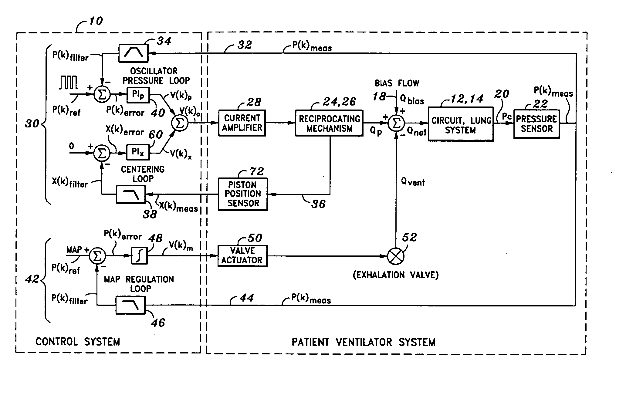
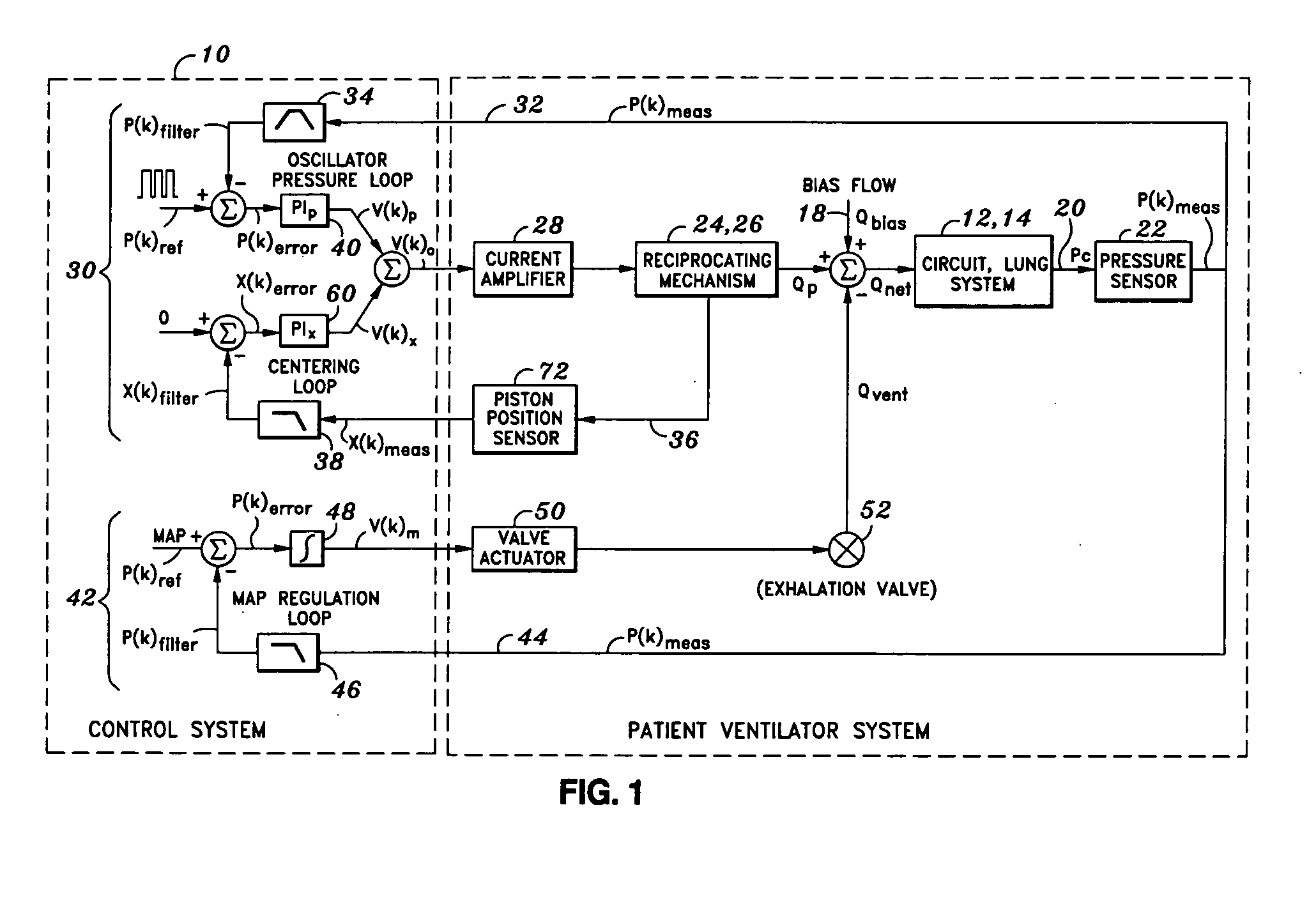
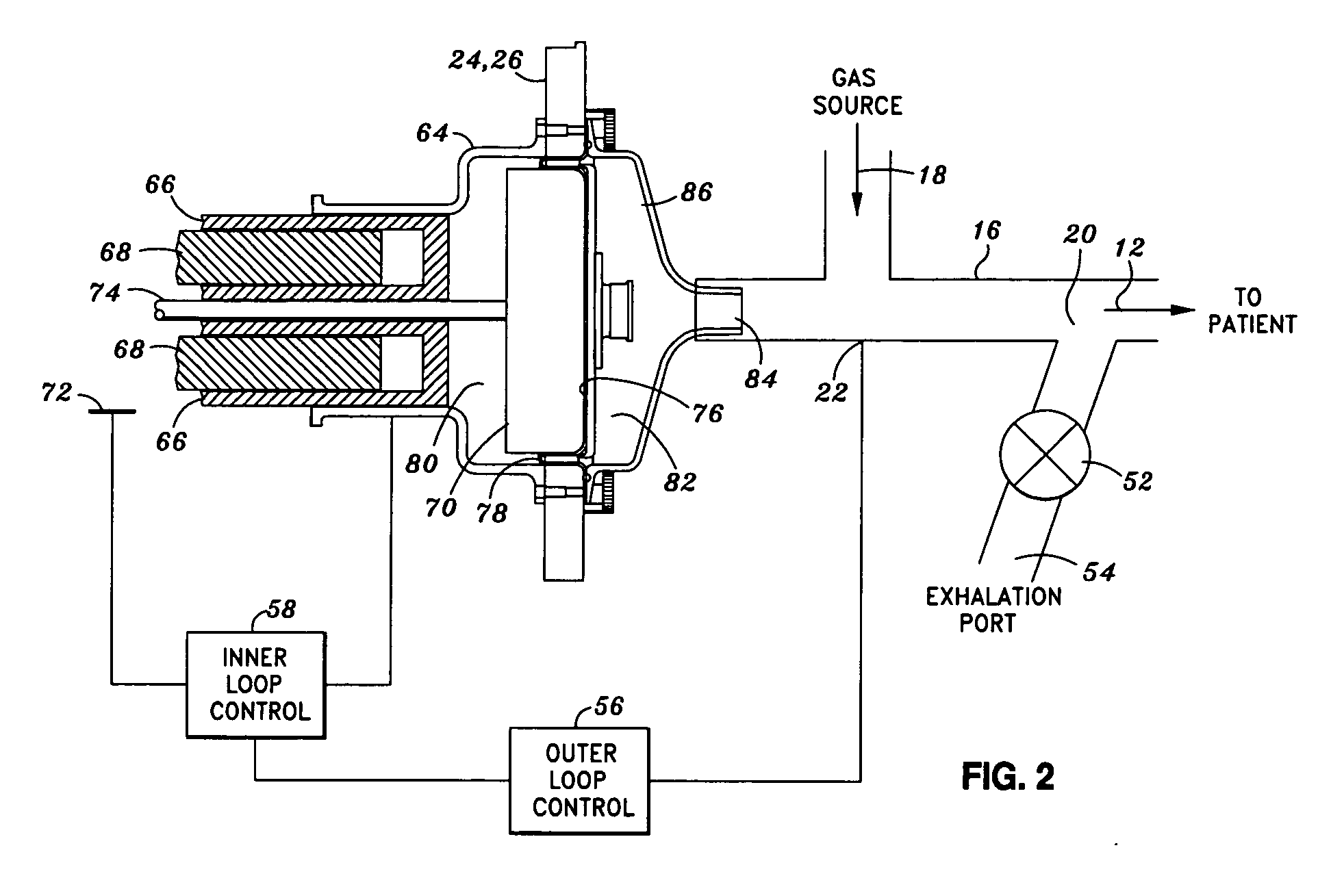
[0029] Referring now to the drawings wherein the showings are for purposes of illustrating the present invention and not for purposes of limiting the same, shown in FIG. 1 is a closed loop control system 10 for a high frequency oscillating ventilator (HFOV) 26. The control system 10 of the present invention is specifically adapted to provide accurate control of pressure oscillations induced by piston 70 reciprocation within the HFOV 26. Furthermore, the control system 10 of the present invention provides a means for accurate centering of the piston 70 which generates the pressure oscillations.

[0030] In addition, the control system 10 of the present invention provides a means for decoupling pressure oscillations from the control of the mean airway pressure (MAP) while maximizing responsiveness of the same. Importantly, the control system 10 achieves the above-noted goals by using feedback of patient circuit pressure Pc and piston 70 position or piston 70 displacement in order to reg...


PUM


Abstract

A control system for a high frequency oscillating ventilator (HFOV) includes and oscillator controller and a mean airway pressure (MAP) controller. The HFOV includes a reciprocating piston which is adapted to generate positive and negative pressure waves for delivery to a patient airway. The oscillator controller comprises a pair of closed loop control circuits including an oscillator pressure loop and a centering loop which are collectively adapted to regulate frequency and amplitude of piston reciprocations and centering of the piston. The MAP controller comprises a closed loop control circuit that is adapted for regulating MAP at the patient utilizing feedback in the form of patient circuit pressure. Likewise, the oscillator controller utilizes patient circuit pressure as well as piston displacement feedback in order to regulate movement of the piston.

Description

CROSS-REFERENCE TO RELATED APPLICATIONS [0001] This application is related to U.S. application Ser. No. 11 / 269,488 entitled HIGH FREQUENCY OSCILLATING VENTILATOR filed on Nov. 8, 2005, the entire contents of which is expressly incorporated by reference herein.STATEMENT RE: FEDERALLY SPONSORED RESEARCH / DEVELOPMENT [0002] (Not Applicable) BACKGROUND [0003] The present invention relates generally to medical equipment, and more particularly, to a closed loop control system for a high frequency oscillating ventilator (HFOV) for producing positive and negative pressure waves in respiratory air that is supplied to a patient. Advantageously, the control system is specifically adapted to allow for accurate control of the pressure oscillations produced by the HFOV while providing a means for accurate control of mean airway pressure (MAP). [0004] As opposed to conventional ventilators which ventilate only during the inhalation phase and which rely on human physiological response for ventilatio...

Claims


Application Information

Patent Timeline
IPC IPC(8): A61M16/00A62B7/00
CPCA61M16/0057A61M16/0096A61M2016/0027A61M16/205A61M2205/3317A61M16/208A61M2205/3306A61M16/0009A61M16/006
Inventor BORRELLO, MICHAEL A.
Owner VYAIRE MEDICAL 211 INC
Learn More