Anti-dust structure for a sliding block of a linear guideway

a technology of anti-dust structure and linear guideway, which is applied in the direction of linear bearings, shafts and bearings, bearings, etc., can solve the problems of high production cost, still some problems to be solved, and consumers still need uninterrupted technology improvement, etc., and achieve the effect of low cost and simple structur

Inactive Publication Date: 2007-09-20
HIWIN TECH
View PDF7 Cites 6 Cited by
  • Summary
  • Abstract
  • Description
  • Claims
  • Application Information

AI Technical Summary

Benefits of technology

[0017]The primary objective of the present invention is to provide a simply structured and low cost anti-dust structure used on a sliding block of a linear guideway.

Problems solved by technology

Although the technology for linear transmission element is developing fast, consumers still need the technology to be improved uninterruptedly.
Therefore, there are still some problems to be solved.
First, in addition to the complicated assembly process, it should use a plurality of screws to fix the anti-dust plate 10, and some anti-dust plates 10 should be fixed by using the oil nozzle structure. Obviously, it is uneconomic since the resultant production cost is pretty high.
Second, the production process is complicated, the producer has to punch the anti-dust plate 10, and then fix the lip portion 11 on it, and the sliding block also needs to be drilled.
Third, the lip portion 11 is easily broken off after bonding, it is impossible to use soft flexible material (soft flexible material is more difficult to be positioned by bonding), therefore, the dust accumulated inside the lip portion 11 still can enter the upper ball groove easily.
Fourth, the lip portion 11 is bonded to the anti-dust plate 10, the lip portion 11 and the anti-dust plate 10 must be replaced together once one of them is broken, and the replacement work requires the user to unscrew the screws with tools. Therefore, the maintenance of the lip portion 11 is not easy.
First, it still needs to use the screws 16 to fix the metal plate 13 and the lip portions 14, the resultant production cost is high.
Second, the production process is still complicated despite the assembly is simple, because the lip portions 14 should be formed by two steps, which involves two materials and many processes.
Third, the pair of lip portions 14 is formed by injection molding, it can't be required, and once it is broken, the whole anti-dust system must be replaced, and the replacement work requires the user to unscrew the screws with tools.
Therefore, the maintenance of the lip portion 11 is not easy.

Method used


Image

  • Anti-dust structure for a sliding block of a linear guideway
  • Anti-dust structure for a sliding block of a linear guideway
  • Anti-dust structure for a sliding block of a linear guideway

Examples


Embodiment Construction

[0030]The foregoing, and additional objects, features and advantages of the present invention will become apparent from the following detailed description of preferred embodiment thereof, taken in conjunction with the accompanying FIGS. 3-6.

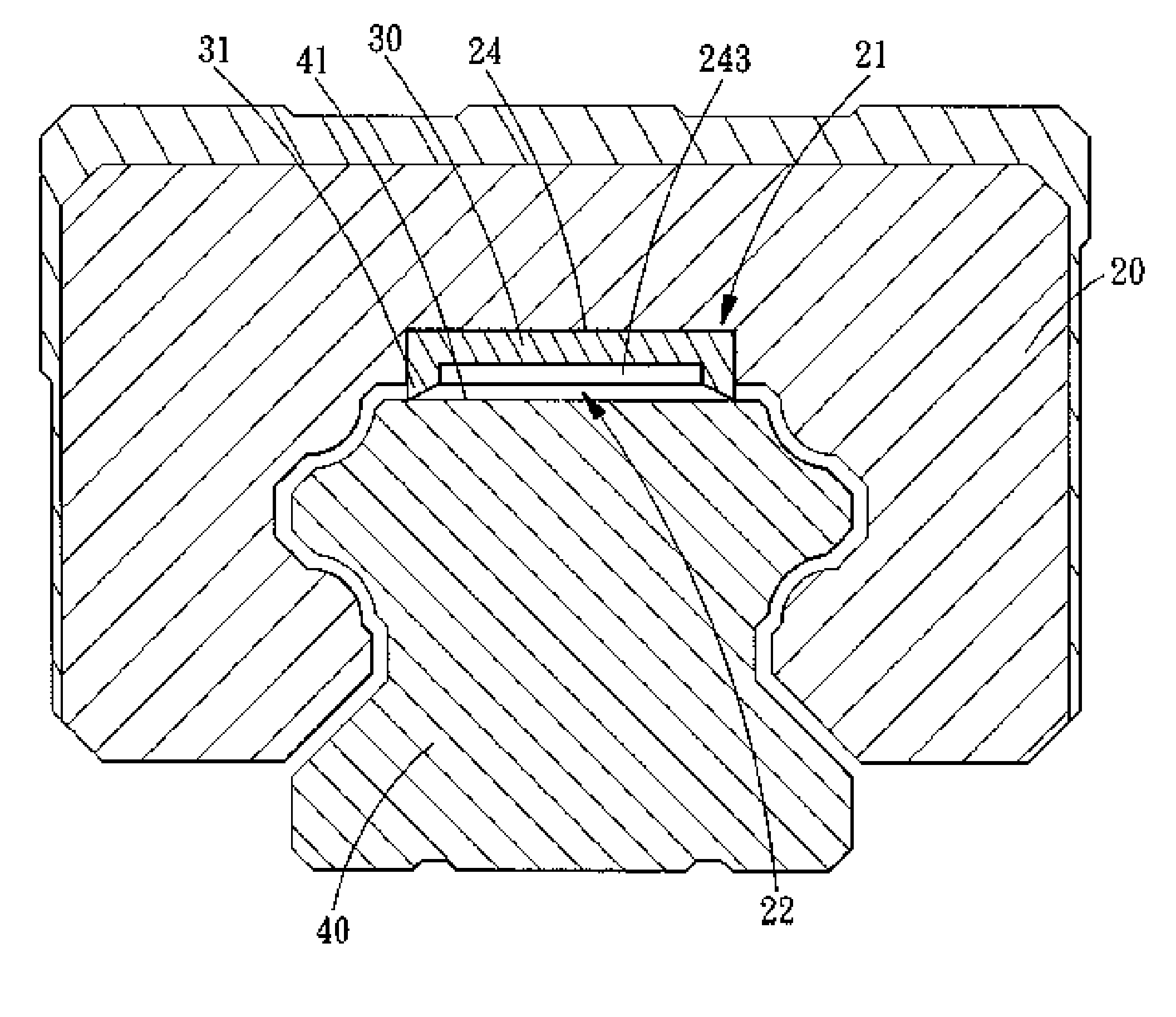
[0031]An anti-dust structure for a sliding block of a linear guideway is fixed on an inner surface 21 of a sliding block 20 slideably mounted on a linear guideway 40. The inner surface 21 is located opposite the top surface 41 of the rail 40. A steel ball retaining portion 22 is assembled on the inner surface 21 of the sliding block 20. A positioning groove 24 is formed in the steel ball retaining portion 22 and includes two longitudinal grooves 241 and two transverse grooves 242. The longitudinal grooves 241 are parallel to the axis of the rail 40, and the two transverse grooves 242 are formed in the inner surface of the end caps 25 fixed at both ends of the sliding block 20. And a protrusion 243 is formed at a lower edge of each of the transver...


PUM


Abstract

An anti-dust structure for a sliding block of a linear guideway comprises a sliding block and a flexible anti-dust strip. A positioning groove is formed in the inner surface of the sliding block and located correspondingly to the upper steel ball groove. The flexible anti-dust strip has a plurality of lip portions that protrude out of the positioning groove, and the lip portions come into contact with the top surface of the rail. In this way, the flexible anti-dust strip can scrape off the grease and dust accumulated on the top surface of the rail at all times, preventing the dust and grease entering the upper steel ball groove via the top surface of the rail, and thus obtaining a better anti-dust function and ensuring the service life of the linear guideway.

Description

BACKGROUND OF THE INVENTION[0001]1. Field of the Invention[0002]The present invention relates to a linear guideway, and more particularly to an anti-dust structure for a sliding block of a linear guideway, which can use the flexible anti-dust strip to scrape off the grease and dust accumulated on the top surface of the rail at any time, preventing the dust and grease entering the upper steel ball groove via the top surface of the rail, and thus obtaining a better anti-dust function and ensuring the service life of the linear guideway.[0003]2. Description of the Prior Art[0004]Since linear transmission products are being applied more and more widely in the modern industry, various linear transmission mechanisms have widely come into human life, manufacturing factory and high science and technology instruments, such as linear guideway, ball screw, and the like. Particularly in a large-scale precision mechanism are usually installed various large and small ball screws or linear guidewa...

Claims


Application Information

Patent Timeline
Patent Type & Authority Applications(United States)
IPC IPC(8): B27G21/00B27G19/00
CPCF16C29/088F16C29/0635F16C29/0647
Inventor LIN, YUN-YIHSU, HSIN-TSUN
Owner HIWIN TECH
Why Eureka
Try Eureka