Semifinished Joint Plate, Joint Plate, Process for Fabricating Joint Plate and Heat Exchanger

a technology of joint plate and heat exchanger, which is applied in the direction of indirect heat exchanger, laminated elements, lighting and heating apparatus, etc., can solve the problems of reducing the dimensional and reducing the dimensional accuracy of the bulging portion. , the effect of reducing the dimensional accuracy

Inactive Publication Date: 2007-09-20
KEIHIN THERMAL TECH CORP
View PDF6 Cites 20 Cited by
  • Summary
  • Abstract
  • Description
  • Claims
  • Application Information

AI Technical Summary

Benefits of technology

[0016] 7) In a heat exchanger comprising a refrigerant inlet header and a refrigerant outlet header arranged side by side in a front-rear direction, and a refrigerant circulating passage for holding the two headers in communication with each other therethrough, the inlet header having a refrigerant inlet at one end thereof, the outlet header having a refrigerant outlet at one end thereof alongside the inlet end, a refrigerant being permitted to flow from the refrigerant inlet into the inlet header and to return to the outlet header through the circulating passage so as to be sent out from the refrigerant outlet, a joint plate joined to both the inlet header and the outlet header and having a refrigerant inlet portion in communication with the refrigerant inlet and a refrigerant outlet portion in communication with the refrigerant outlet, the joint plate being made from a semifinished joint plate according to par. 1) by bending a portion of the semifinished plate above the upper slit width adjusting portion and a portion thereof below the lower slit width adjusting portion in the direction of width of the semifinished joint plate to thereby shorten the semifinished plate in the front-rear direction, decrease the width in the front-rear direction of the slit and cause the inlet portion and the outlet portion to communicate with the inlet of the inlet header and the outlet of the outlet header respectively.
[0040] With the heat exchanger according to par. 16), the separating means functions to give improved uniformity to all the heat exchange tubes joined to the inlet header in the quantities of refrigerant flowing therethrough, further rendering all the heat exchange tubes joined to the outlet header uniform in the quantities of refrigerant flowing therethrough and enabling the exchanger to achieve a further improved heat exchange efficiency.

Problems solved by technology

In the event of short-circuiting, the refrigerant admitted through the refrigerant inlet pipe flows into the refrigerant outlet pipe without flowing through the circulating passage, failing to contribute to refrigeration in any way and resulting in seriously impaired refrigeration performance.
However, since the short circuit preventing slit in the joint plate of the publication is formed by press work, the lower limit to the slit width is restricted, and the slit can not be made if the inlet portion and the outlet portion are spaced apart by a small distance.
This nevertheless results in an increased number of components, entailing the problem that the joint plates will not be efficiently incorporated into the evaporator to be fabricated.

Method used


Image

  • Semifinished Joint Plate, Joint Plate, Process for Fabricating Joint Plate and Heat Exchanger
  • Semifinished Joint Plate, Joint Plate, Process for Fabricating Joint Plate and Heat Exchanger
  • Semifinished Joint Plate, Joint Plate, Process for Fabricating Joint Plate and Heat Exchanger

Examples


second embodiment

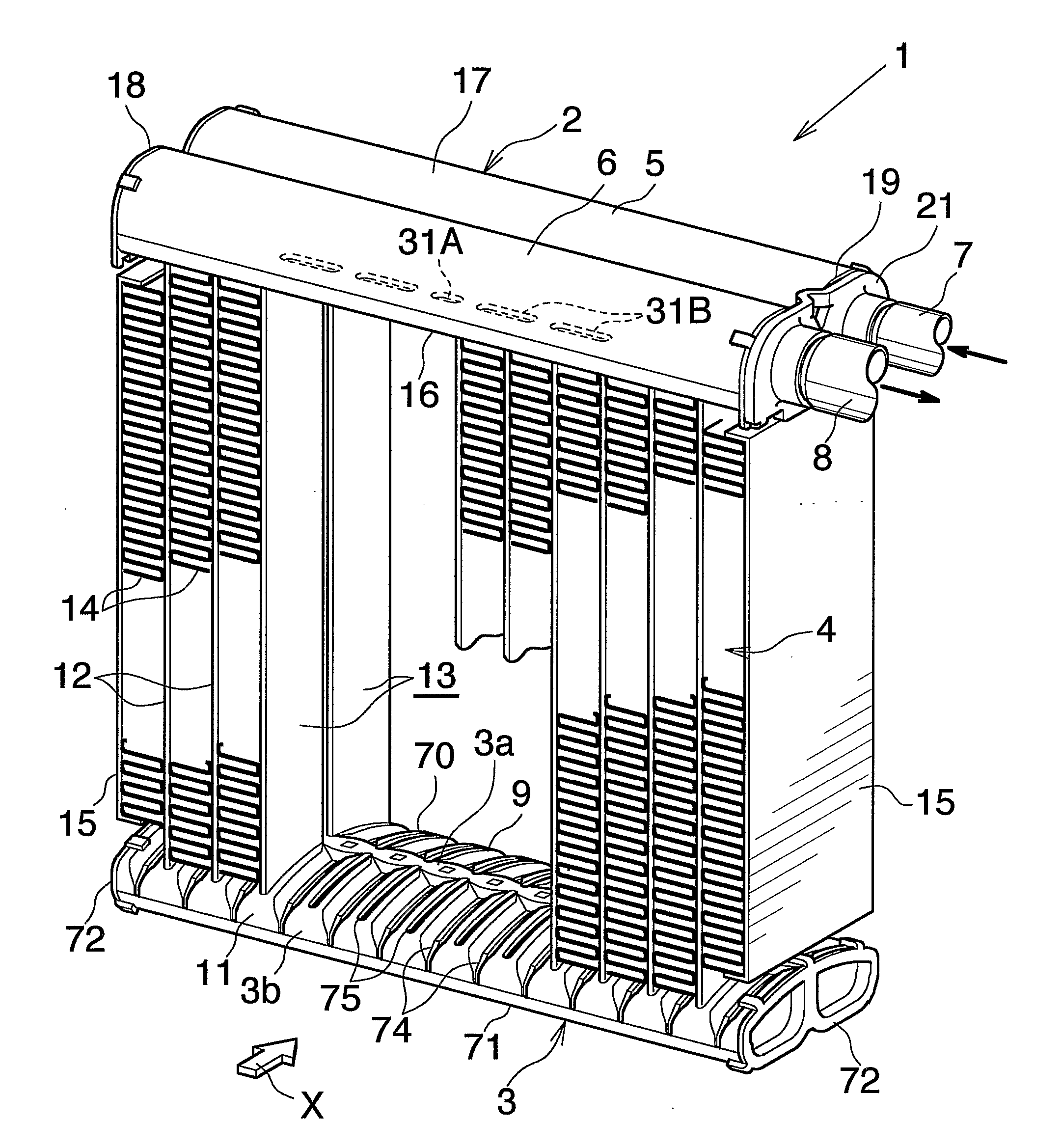
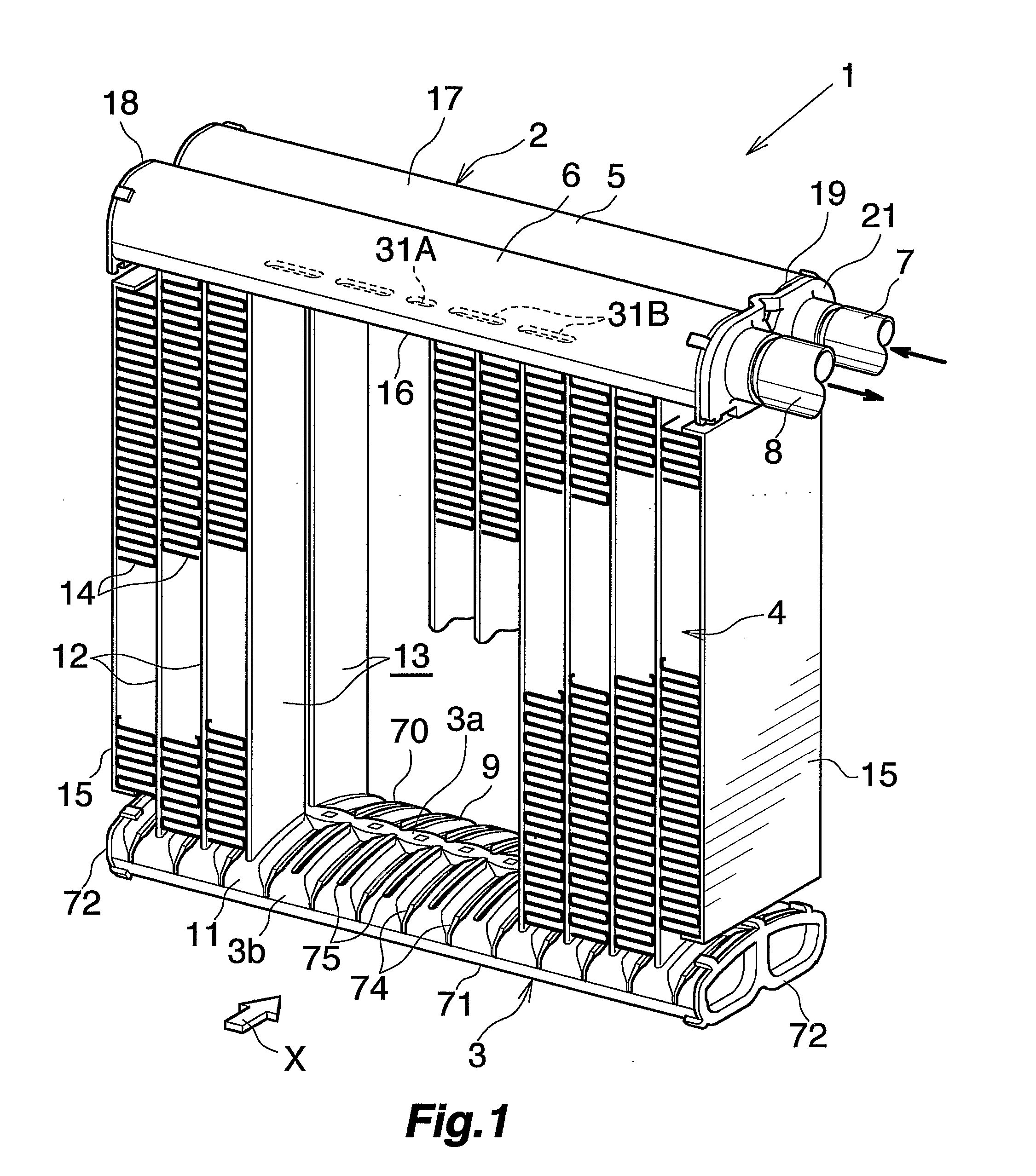
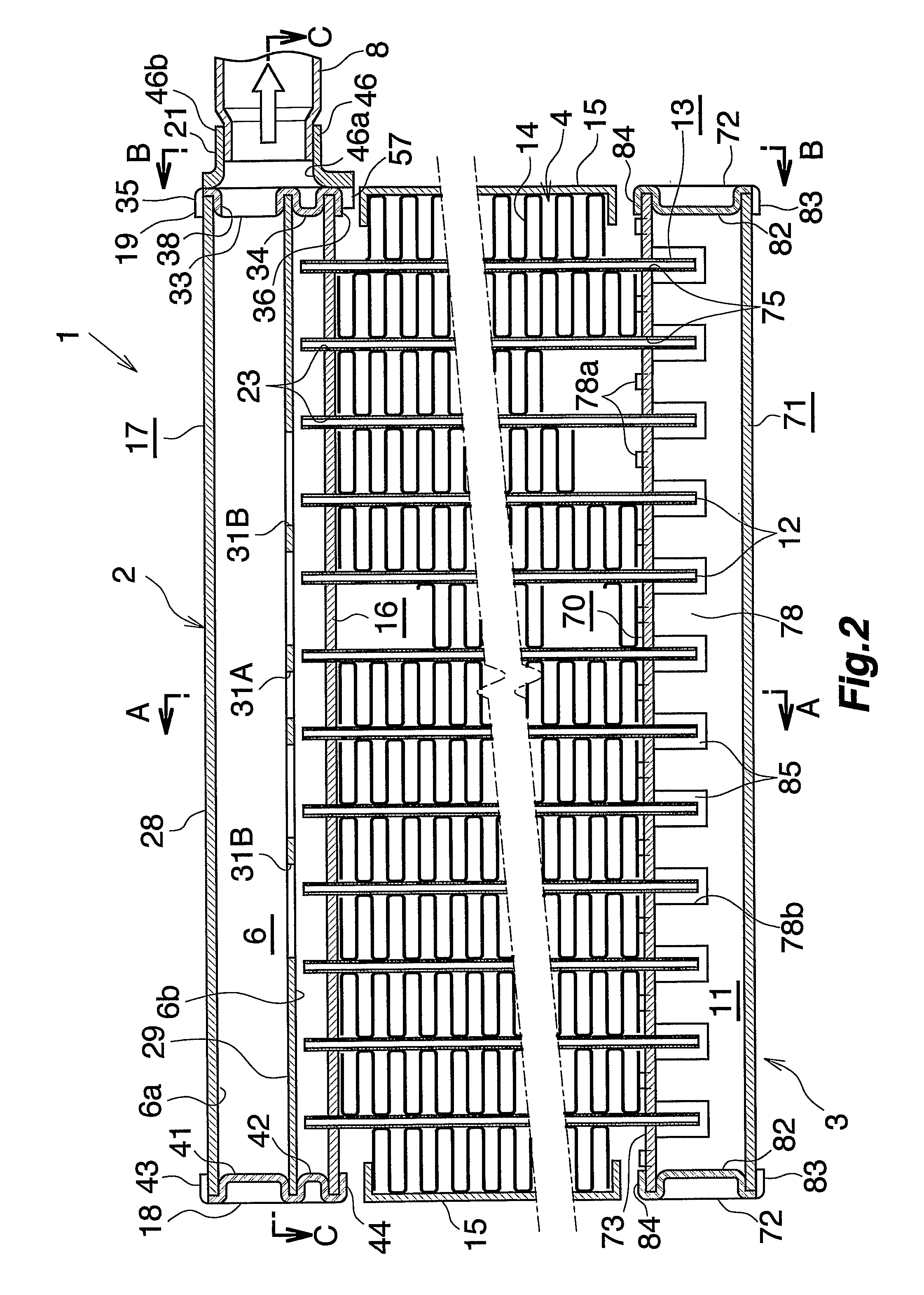
[0093]FIG. 11 shows evaporator to which the heat exchanger of the invention is applied. Throughout FIGS. 1 to 11, like parts are designated by like reference numerals.

[0094]FIG. 11 shows an evaporator 90 which comprises a refrigerant inlet header 91 and a refrigerant outlet header 92 which are arranged side by side from the front rearward, a first intermediate header 93 provided above the inlet header 91 and spaced apart therefrom, a second intermediate header 94 provided on the left side of the first intermediate header 93, a third intermediate header 95 disposed below and spaced apart from the second intermediate header 94 and positioned on the left side of the inlet header 91, a fourth intermediate header 96 provided alongside the third intermediate header 95 on the rear side thereof and positioned on the left side of the outlet header 92, a fifth intermediate header 97 provided above and spaced apart from the fourth intermediate header 96 and disposed alongside the second interm...

first embodiment

[0095] The inlet header 91, outlet header 92, third intermediate header 95 and fourth intermediate header 96 are formed by separating one tank 99 into four portions arranged from the front rearward and from the left to the right. The tank 99 is similar to the refrigerant turn tank 3 of the first embodiment and comprises a first member 70 and a second member 71. The tank 99 differs from turn tank 3 with respect to the following. The tank 99 is divided into a front and a rear space by a partition wall 78 inside the tank, and each of these spaces is divided into a left and a right portion by an aluminum partition plate 101 disposed at the midportion with respect to the left-right direction, whereby four headers 91, 92, 95, 96 are provided. The portion of the partition wall 78 on the right side of the partitions plate 101 has no cutouts 78b, and the inlet header 91 is held out of communication with the outlet header 92. A cap 72 for the right-end openings has a refrigerant inlet 102 for...


PUM

PropertyMeasurementUnit
widthaaaaaaaaaa
lengthaaaaaaaaaa
widthaaaaaaaaaa

Abstract

A semifinished joint plate 60 has a refrigerant inlet portion 45 and a refrigerant outlet portion 46 spaced apart in the front-rear direction. The semifinished plate 60 has an upwardly or downwardly extending slit 61 formed between the inlet portion 45 and the outlet portion 46, and slit width adjusting portions 62, 63 extending through the thickness of the plate 60, having a larger width than the slit 61 and communicating respectively with the upper and lower ends of the slit 61. A portion of the semifinished plate 60 above the upper adjusting portion 62 and a portion thereof below the lower adjusting portion 63 are bent to shorten the plate

Description

CROSS REFERENCE TO RELATED APPLICATION [0001] This application is an application filed under 35 U.S.C. §111(a) claiming the benefit pursuant to 35 U.S.C. §119(e) (1) of the filing date of Provisional Application No. 60 / 559,961 filed Apr. 7, 2004 pursuant to 35 U.S.C. §111(b).TECHNICAL FIELD [0002] The present invention relates to semifinished joint plates, joint plates, a process for fabricating joint plates, and heat exchangers, and more particularly to semifinished joint plates for making joint plates for use in heat exchangers useful as evaporators for motor vehicle air conditioners which are refrigeration cycles to be installed in motor vehicles, joint plates, a process for fabricating the joint plate and heat exchangers. [0003] The term “aluminum” as used herein and in the appended claims includes aluminum alloys in addition to pure aluminum. The downstream side (the direction indicated by the arrow X in FIG. 1, and the right-hand side of FIGS. 4, 5 and 8) of the air to be pass...

Claims


Application Information

Patent Timeline
Patent Type & Authority Applications(United States)
IPC IPC(8): F28F3/06B60H1/00F28F9/02B60H1/32F25B39/02F28D1/053F28F9/04F28F21/08
CPCF25B39/022F25B2500/01F28D1/05391Y10T29/49393F28F9/0214F28F9/0246F28F2220/00F28F9/0204
Inventor HIGASHIYAMA, NAOHISATSUNODA, KENJI
Owner KEIHIN THERMAL TECH CORP
Why Eureka
Try Eureka