Tray assembly for spindle motor with aerodynamic bearing

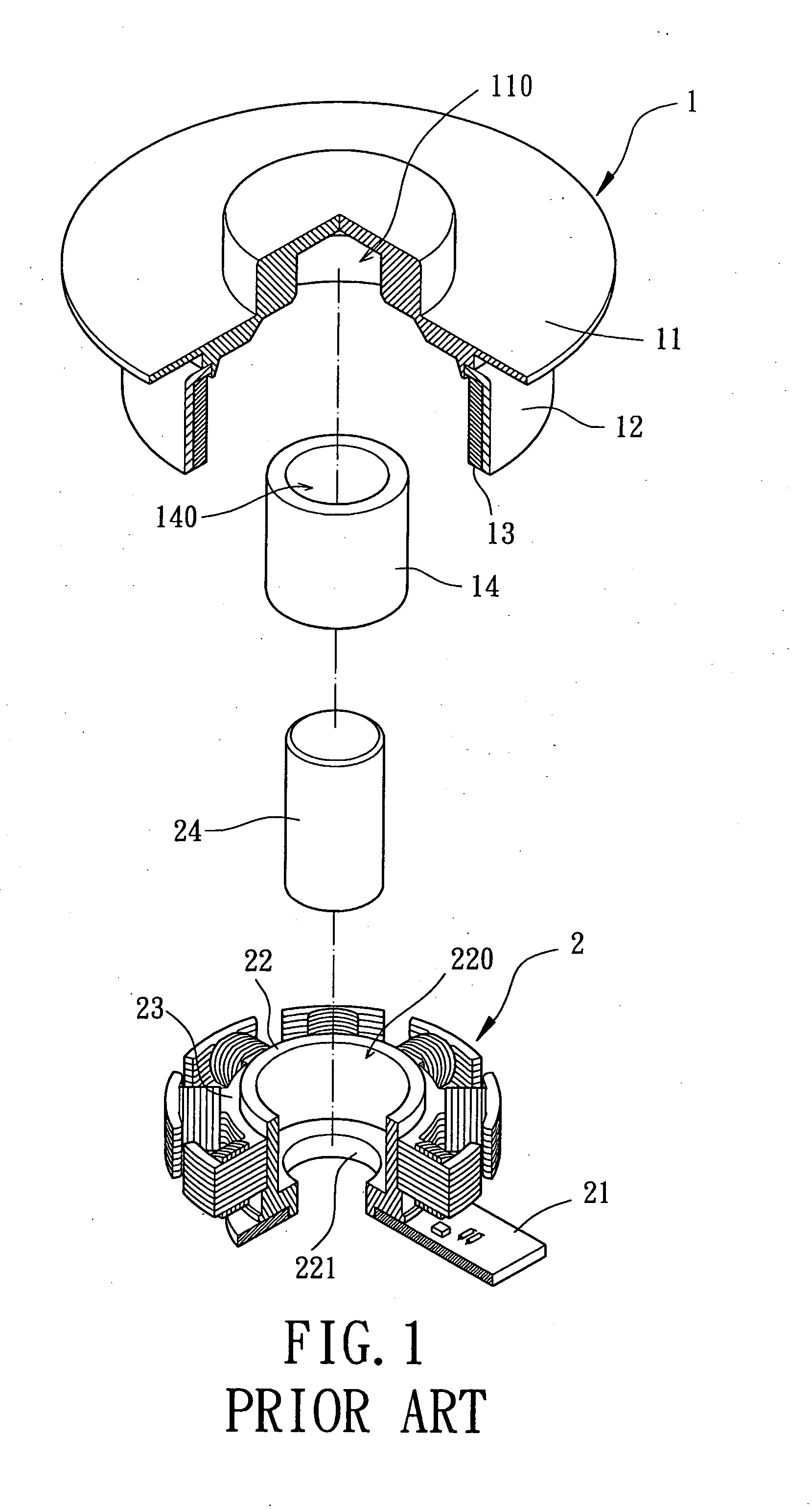
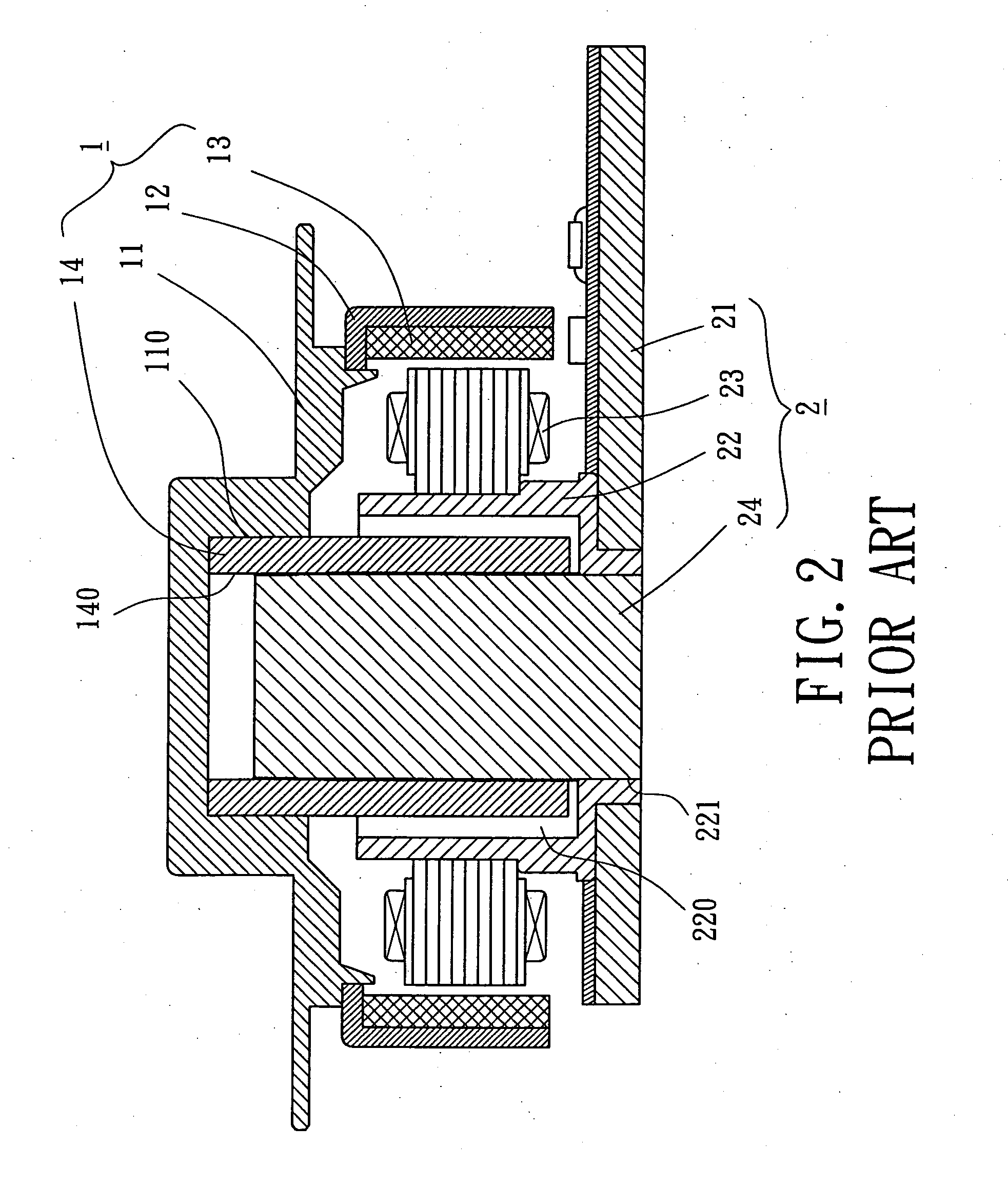
a technology of aerodynamic bearing and assembly, which is applied in the direction of mechanical energy handling, instruments, record information storage, etc., can solve the problems of reducing the size of the aerodynamic rotational sleeve b>14, the overall size, and the adverse effect of balancing weight and assembly product yield, so as to increase the yield of assembled products

Inactive Publication Date: 2007-09-20
SUNONWEALTH ELECTRIC MACHINE IND
View PDF9 Cites 8 Cited by
  • Summary
  • Abstract
  • Description
  • Claims
  • Application Information

AI Technical Summary

Benefits of technology

[0010] An object of the present invention is to provide a tray assembly for a spindle motor with an aerodynamic bearing, wherein the yield of assembled products is increased.
[0011] Another object of the present invention is to provide a tray assembly for a spindle motor with an aerodynamic bearing, wherein the balance adjustment of the tray assembly is more flexible.
[0012] A further object of the present invention is to provide a tray assembly for a spindle motor with an aerodynamic bearing, wherein the rotational balance of the tray assembly is improved.

Problems solved by technology

Further, in a case that the aerodynamic rotational sleeve 14 is mounted in the engaging hole 110 by gluing, excessive or insufficient amount of glue or uneven gluing would lead to adverse affect to the balancing weight and to the yield of assembled products.
Furthermore, the above-mentioned assembling method could not allow further reduction of the size of the aerodynamic rotational sleeve 14 and of the overall size.
Namely, minimization of the spindle motor is not possible.
In a case that air in the gap leaks, the operational effect of the aerodynamic rotational sleeve 14 and the aerodynamic fixed shaft 24 is adversely affected to a large extent.

Method used


Image

  • Tray assembly for spindle motor with aerodynamic bearing
  • Tray assembly for spindle motor with aerodynamic bearing
  • Tray assembly for spindle motor with aerodynamic bearing

Examples


first embodiment

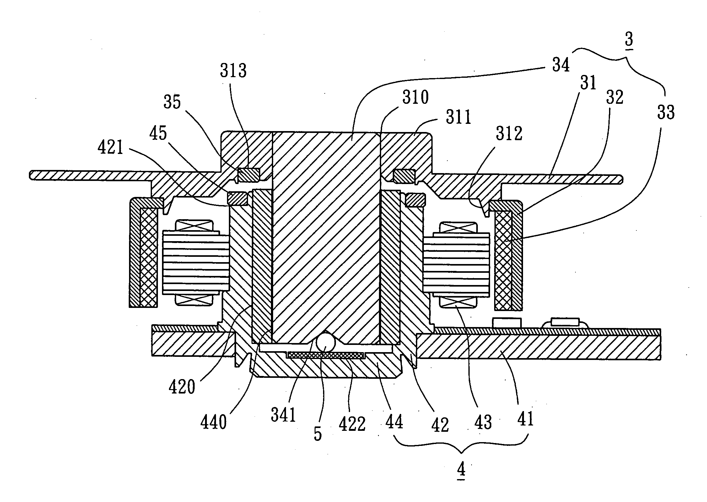
[0038] Referring to FIG. 3, a tray assembly 3 in accordance with the present invention is rotatably mounted on a fixed portion 4. An object (not shown) such as an optical disk, a magnetic disk, or a floppy disk can be mounted on a tray 31 of the tray assembly 3. The fixed portion 4 is fixed inside an optical disc drive (not shown), a magnetic disk drive (not shown), or a floppy disc drive (not shown). The fixed portion 4 supports and drives the tray. 31 to turn.

[0039] The tray assembly 3 comprises the tray 31, a rotor housing 32, a permanent magnet 33, and an aerodynamic rotational shaft 34. The tray 31 is substantially a disc and includes an engaging hole 310 in a center of an underside thereof. A flange 311 is formed on an upper side of the tray 31, with the engaging hole 310 extending through the flange 311. An engaging area of an inner circumference of the engaging hole 310 is thus increased. A coupling flange 312 is formed on an underside of the tray 31. The rotor housing 32 is...

second embodiment

[0045]FIGS. 5 and 6 show the tray assembly 3 of the present invention. In this embodiment, the tray assembly 3 further comprises a first balancing plate 35, a second balancing plate 45, and a ball 5 for assisting in rotational balance of the tray assembly 3.

[0046] More specifically, the first balancing plate 35 may be a magnetic balancing plate such as a magnetic ring, and the second balancing plate 45 may be a magnetically conductive balancing plate such as an iron ring. In an alternative example, the first balancing plate 35 may be a magnetically conductive balancing plate and the second balancing plate 45 may be a magnetic balancing plate. In another alternative example, both the first and second balancing plates 35 and 45 are magnetic balancing plates, with opposite poles respectively provided on opposed surfaces respectively of the first and second balancing plates 35 and 45.

[0047] The tray 31 includes an engaging portion 313 on the underside thereof. Preferably, the engaging ...


PUM


Abstract

A tray assembly for a spindle motor includes a tray and an aerodynamic rotational shaft. The tray includes an engaging hole in a center thereof. The aerodynamic rotational shaft includes an outer circumference with a smooth surface. An end of the aerodynamic rotational shaft is engaged in the engaging hole of the tray, with the outer circumference of the end of the aerodynamic rotational shaft engaged with an inner circumference of the engaging hole of the tray by forcibly fitting, allowing precise control and adjustment of an engaging relationship between the aerodynamic rotational shaft and the tray.

Description

BACKGROUND OF THE INVENTION [0001] 1. Field of the Invention [0002] The present invention relates to a tray assembly for a spindle motor. More particularly, the present invention relates to a tray assembly for a spindle motor with an aerodynamic bearing. [0003] 2. Description of Related Art [0004]FIGS. 1 and 2 illustrate a conventional tray assembly for a spindle motor with an aerodynamic bearing. The tray assembly 1 is rotatably mounted on a fixed portion 2 and comprises a tray 11, a rotor housing 12, a permanent magnet 13, and an aerodynamic rotational sleeve 14. The tray 11 is substantially a disc and includes an engaging hole 110 in a center of an underside thereof for securely receiving an end of the aerodynamic rotational sleeve 14. The rotor housing 12 is substantially inverted bowl-like and mounted below the tray 11. The permanent magnet 13 is fixed to an inner circumference of the rotor housing 12. The aerodynamic rotational sleeve 14 includes an aerodynamic hole 140. [0005...

Claims


Application Information

Patent Timeline
Patent Type & Authority Applications(United States)
IPC IPC(8): H02K7/00H02K5/16H02K21/12
CPCG11B17/028G11B19/2009H02K7/09H02K7/085H02K5/1675
Inventor HORNG, ALEXCHEN, KUO-HSIANG
Owner SUNONWEALTH ELECTRIC MACHINE IND
Why Eureka
Try Eureka