
Spread spectrum modulation of a clock signal for reduction of electromagnetic interference

a clock signal and spectrum modulation technology, applied in the field of oscillator clock sources, can solve the problems of electromagnetic interference generation by regulators, interference from switching regulators that differ from design to design, and each of these techniques has drawbacks

Active Publication Date: 2007-09-20
ANALOG DEVICES INT UNLTD
View PDF3 Cites 28 Cited by
  • Summary
  • Abstract
  • Description
  • Claims
  • Application Information

AI Technical Summary

Benefits of technology

The patent describes a circuit that generates a spread spectrum frequency modulated oscillator. It includes a reference component, a controlled oscillator, and two circuits that control the frequency of the oscillator. One circuit controls the rate at which the frequency changes, while the other circuit controls the amount of frequency change. This circuit allows for the generation of a stable and secure frequency modulation signal.

Problems solved by technology

Electronic devices, such as switching regulators often generate electromagnetic interference which can be detrimental to the operation of electronic circuits in which such devices are employed.
Consequently, the interference from a switching regulator differs from design to design.
However, each of these techniques has drawbacks.
This “amplitude modulation” could easily corrupt the operation of electronic circuits, a result which nullifies the benefits of the sinusoidal modulation.
However, the difficulty with random modulation lies in the generation of an optimal random signal.
Too much filtering, however, will negate the benefit of random modulation.

Method used


Image

  • Spread spectrum modulation of a clock signal for reduction of electromagnetic interference
  • Spread spectrum modulation of a clock signal for reduction of electromagnetic interference
  • Spread spectrum modulation of a clock signal for reduction of electromagnetic interference

Examples


Embodiment Construction

[0015] A spread spectrum frequency modulated oscillator circuit is described which generates a wide range of frequencies, exhibiting random frequency modulation which is fast enough to reduce electromagnetic interference (EMI), yet able to be tracked reliably by a device using the oscillator circuit, such as a switching regulator.

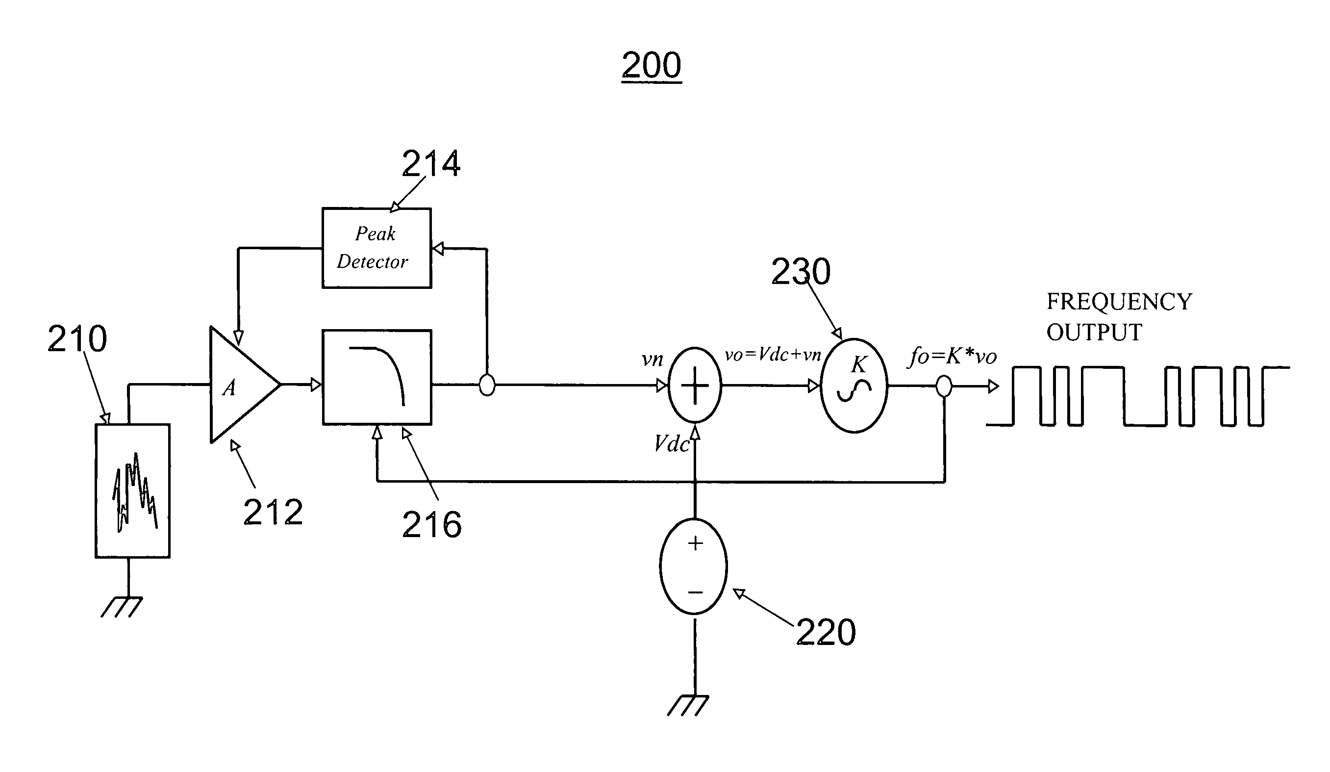
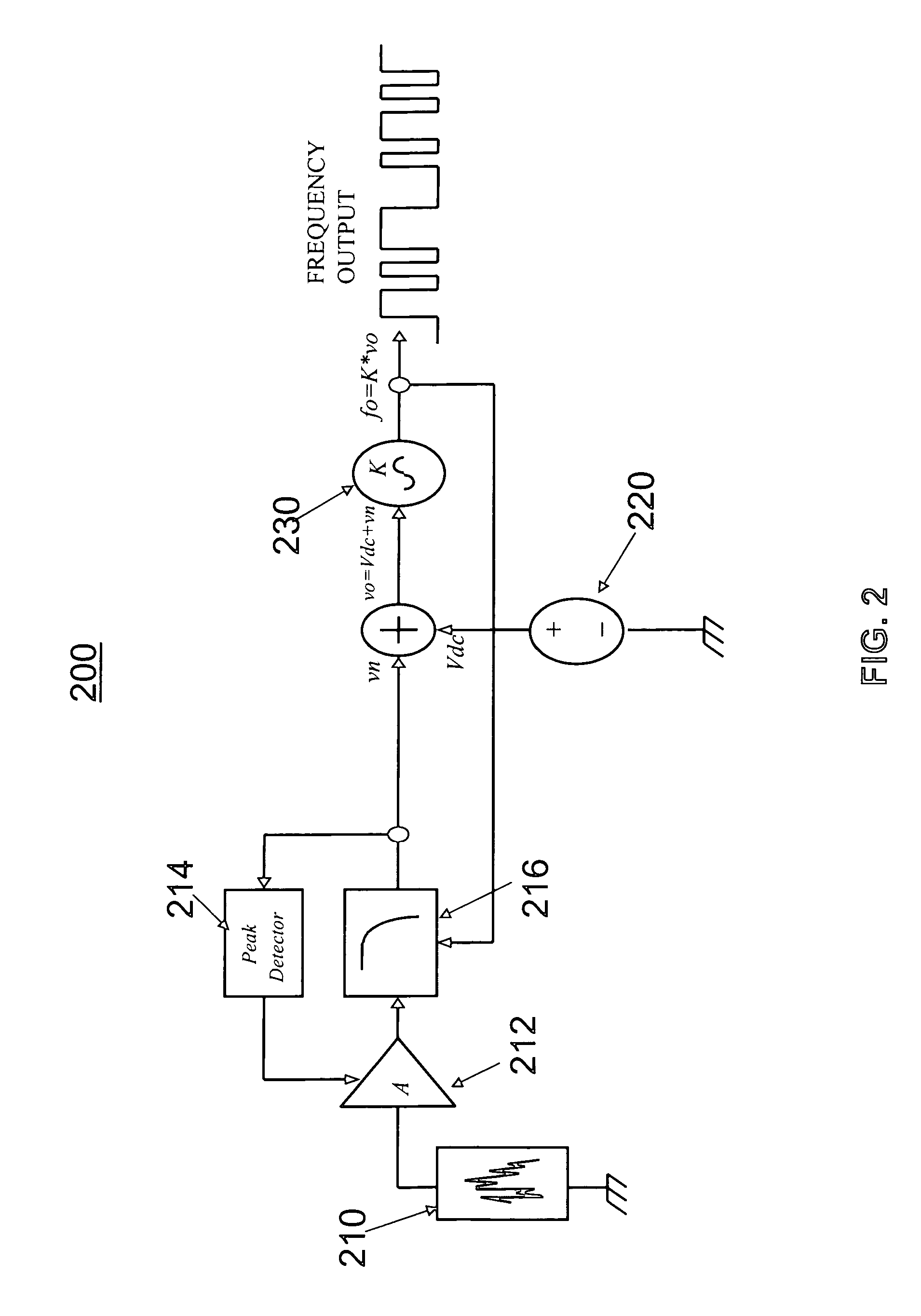
[0016]FIG. 2 is a diagram of an oscillator circuit 200, in accordance with one embodiment of the invention. Oscillator circuit 200 includes a voltage controlled oscillator (VCO) 230, whose output frequency is controlled by a DC source 220 which supplies a constant voltage for setting the mean output frequency of the VCO, and a random voltage source 210 which produces a random voltage signal to modulate, or “dither” the VCO frequency. While voltage signals are used in FIG. 1 to control the oscillator, other signals may be used, such as currents or numbers.

[0017] The generated random voltage signal is added to the supplied constant voltage signal to produce...


PUM


Abstract

A spread spectrum frequency modulated oscillator circuit usable as a clock comprises a reference component such as a resistor, a voltage controlled oscillator and a first circuit coupled to the reference component and voltage controlled oscillator and configured to supply a first control signal to the oscillator to cause the oscillator to oscillate at a frequency corresponding to a value of the reference component. A second circuit configured to supply a random signal to the oscillator causes the frequency of the oscillator to dither. To cause the oscillator to exhibit random frequency modulation that is fast enough to reduce EMI but not too fast for controlled devices such as switching regulators to track, the oscillator includes a third circuit configured to control (1) a rate of change of the oscillator frequency such that the rate of change is a fixed percentage of the oscillator frequency, and (2) an amount of frequency change in the oscillator frequency such that the amount of frequency change is a fixed percentage of the oscillator frequency.

Description

TECHNICAL FIELD [0001] This disclosure relates generally to oscillator clock sources, and more particularly to improving electromagnetic interference by frequency modulating a clock using spread spectrum frequency modulation. BACKGROUND DESCRIPTION [0002] Electronic devices, such as switching regulators often generate electromagnetic interference which can be detrimental to the operation of electronic circuits in which such devices are employed. Switching regulators translate all input voltage at one level to an output voltage at another. Energy from an input voltage source is stored in an inductor or capacitor and then transferred, or switched, to the output. Energy transfer is repeated at a rate determined by the clock source of the regulator. The switching action generates interference, the energy of which is concentrated at frequencies which are harmonics of the clock source. [0003] The output of a switching regulator is a DC level signal plus interference created by clock-contr...

Claims


Application Information

Patent Timeline
Patent Type & Authority Applications(United States)
IPC IPC(8): H03L7/00
CPCH04B15/04
Inventor KULTGEN, MICHAEL
Owner ANALOG DEVICES INT UNLTD
Learn More