Method and apparatus for signal detection

Active Publication Date: 2007-09-20
MOTOROLA SOLUTIONS INC
View PDF10 Cites 3 Cited by
  • Summary
  • Abstract
  • Description
  • Claims
  • Application Information

AI Technical Summary

Problems solved by technology

As is evident, any false alarm will cause the equipment to be unnecessarily blocked out of

Method used


Image

  • Method and apparatus for signal detection
  • Method and apparatus for signal detection
  • Method and apparatus for signal detection

Examples


Example

DETAILED DESCRIPTION OF THE DRAWINGS

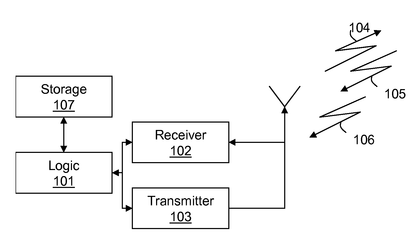
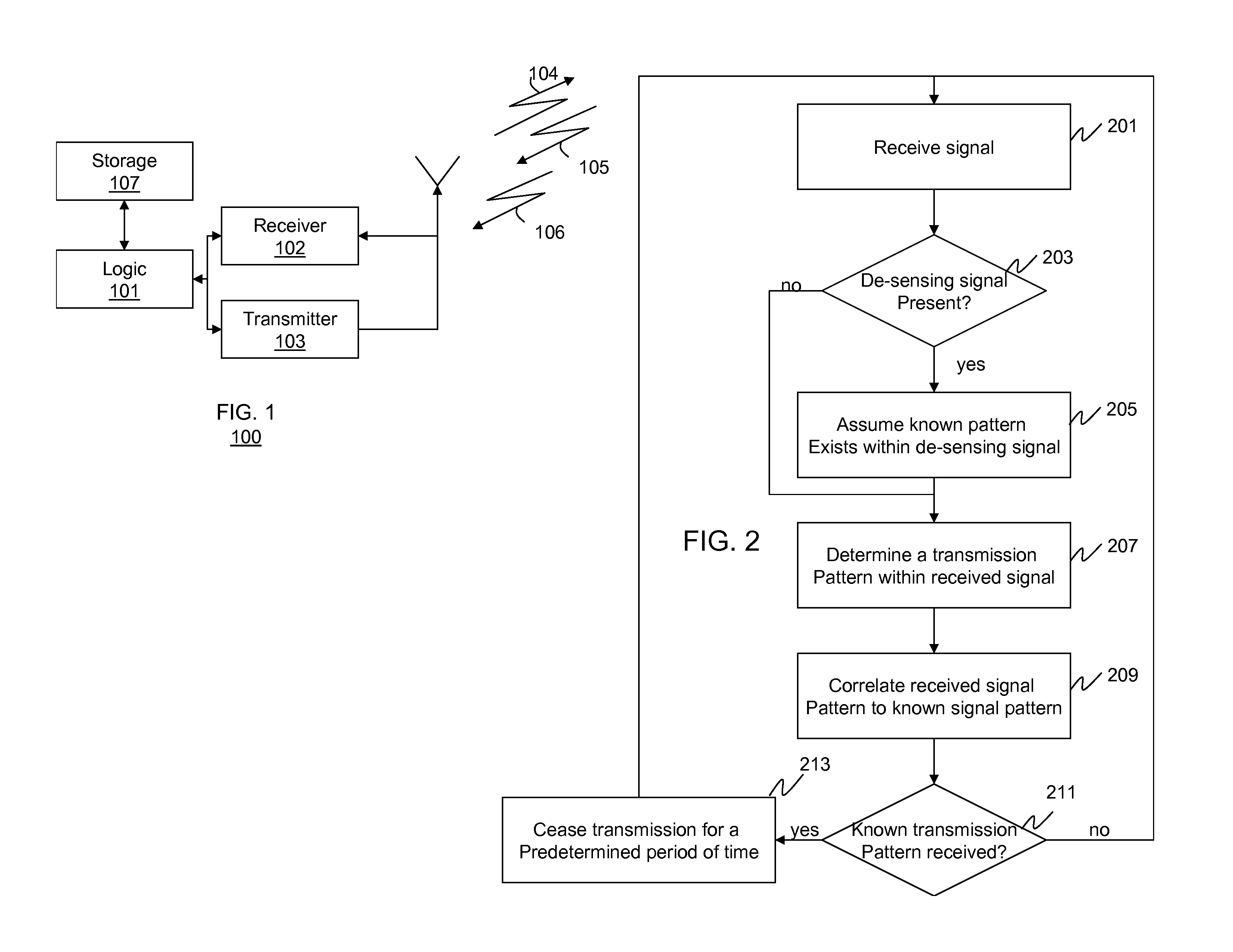
[0006] To address the above-mentioned need, a method and apparatus for signal detection is provided herein. During operation logic circuitry will determine if a de-sensing signal exists within any received signal and, if a de-sensing signal exists, it will be assumed that a portion of a radar pattern exists where the de-sensing signal exists within the signal. Any received signal pattern is then correlated to possible radar transmission patterns (which are known beforehand) to determine if a radar transmission pattern was received. If a known transmission pattern was received then logic circuitry will prevent further transmission.

[0007] The present invention encompasses a method for detecting known signal patterns. The method comprises the steps of receiving a signal, determining if a de-sensing signal exists within the signal, and if the de-sensing signal exists, then assuming that a portion of a known signal pattern exists where the de-sensing...


PUM


Abstract

A method and apparatus for signal detection is provided herein. During operation logic circuitry will determine if a de-sensing signal exists within any received signal and, if a de-sensing signal exists, then it will be assumed that a radar pattern exists where the de-sensing signal exists within the signal. Any received signal pattern is then correlated to known radar transmission pattern in order to determine whether or not a radar transmission pattern was received. If a known transmission pattern was received then logic circuitry will prevent further transmission.

Description

FIELD OF THE INVENTION [0001] The present invention relates generally to signal detection, and in particular, to a method and apparatus for signal detection within a communication system. BACKGROUND OF THE INVENTION [0002] According to the US Electronic Code of Federal Regulations—Title 47—Part 15—Section 15.407 (h) (2), devices operating in the 5.25-5.35 GHz and 5.47-5.725 GHz bands shall employ a radar detection mechanism to detect the presence of radar systems and to avoid co-channel operation with radar systems. In particular, conformance requires that unlicensed equipment operating in the 5.25-5.35 GHz and 5.47-5.725 GHz bands be able to detect Bin 5 radar signals with a minimum successful detection probability of 80% (out of 30 trials) at the end of the 12-second long test signal of each trial. After detecting the Bin 5 radar signal, the equipment must vacate the frequency within 10 seconds and refrain from transmitting in the same frequency band for the next 30 minutes. As is...

Claims


Application Information

Patent Timeline
IPC IPC(8): H04B1/00H04B17/00G01S13/00
CPCG01S7/021H04B17/318H04B2215/062H04B15/02
Inventor D'AMICO, THOMAS V.LIU, PEIJUANPETERSON, ROGER L.
Owner MOTOROLA SOLUTIONS INC
Why Eureka
Try Eureka