Liquid crystal driving device

a driving device and liquid crystal technology, applied in the direction of electric digital data processing, instruments, computing, etc., can solve the problems of image exit, remaining and incomplete change in the voltage to be applied to the liquid crystal panel. achieve the effect of lowering the luminan

Active Publication Date: 2007-09-20
NEC LCD TECH CORP
View PDF11 Cites 19 Cited by
  • Summary
  • Abstract
  • Description
  • Claims
  • Application Information

AI Technical Summary

Benefits of technology

[0066]With still another configuration, even if a voltage exceeding an extreme value of transmittance of the liquid crystal panel is applied, neither reverse rotation of a liquid crystal substance caused by its viscosity nor a stable s

Problems solved by technology

Conventionally, a liquid crystal display device has a problem of a phenomenon in which an image leaves a trail when moving images are displayed.
This phenomenon is caused by a delay in response of a liquid crystal element.
Due to this, the change in the voltage to be applied to the liquid crystal panel is not complete during the lapse of one fresh rate and, as a result, a remaining change in the voltage to be applied to the liquid crystal panel occurs during a subsequent refresh period.
In the conventional liquid crystal driving method shown in FIG. 14, it is possible that the overshooting driving operation is performed in a manner to correspond to all voltages within the applied displaying voltages, however, a decrease in the number of gray-level values corresponding to a narrowed range of the applied displaying voltages causes a narrow dynamic range of display gray-level values in the liquid crystal panel, thus resulting in a decrease in image contrast.
Thus, in the liquid crystal driving method shown in FIG. 12, in the case of transition to the highest gray-level value or the lowest gray-level value, the overshooting operation is impossible,

Method used


Image

  • Liquid crystal driving device
  • Liquid crystal driving device
  • Liquid crystal driving device

Examples


first embodiment

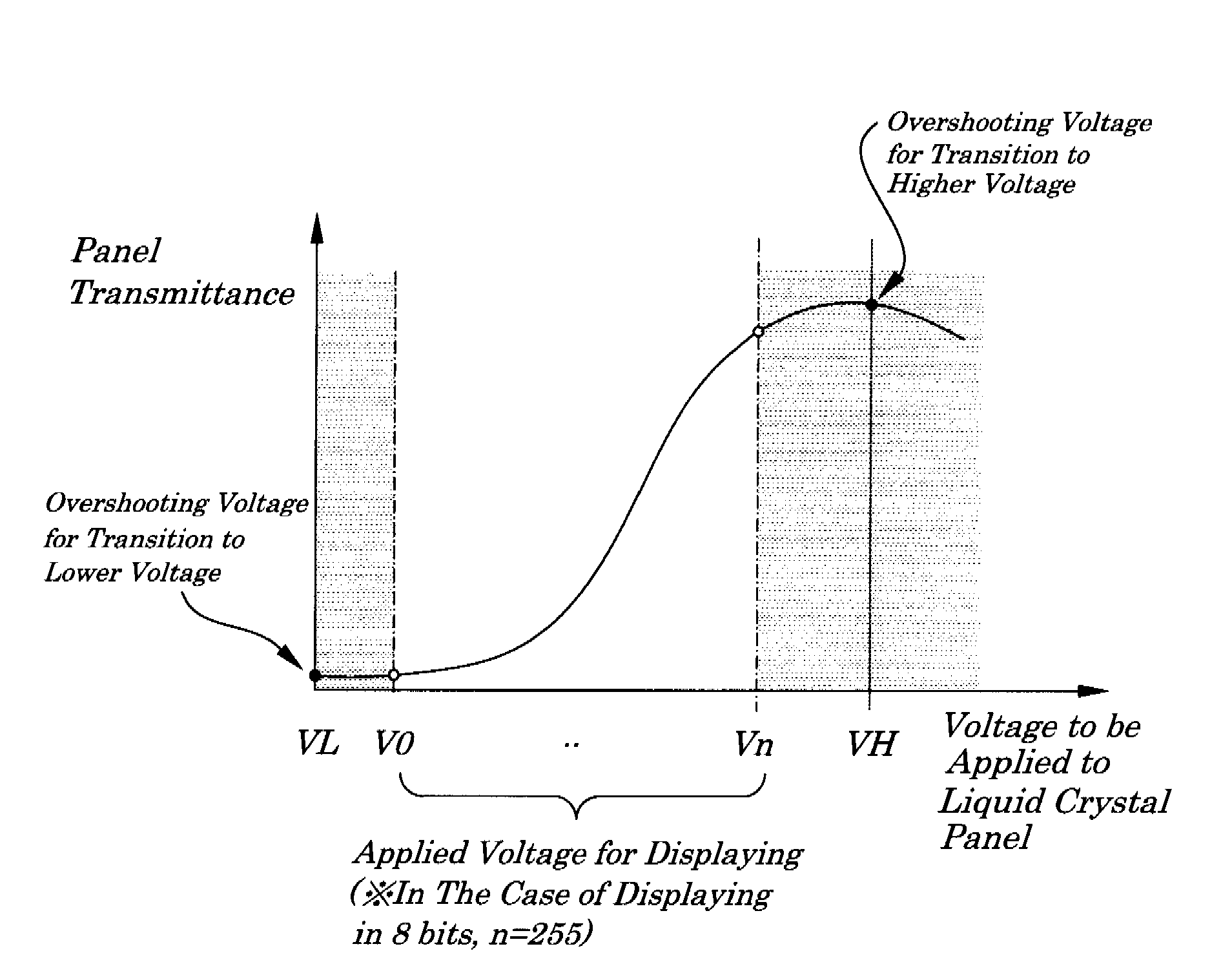
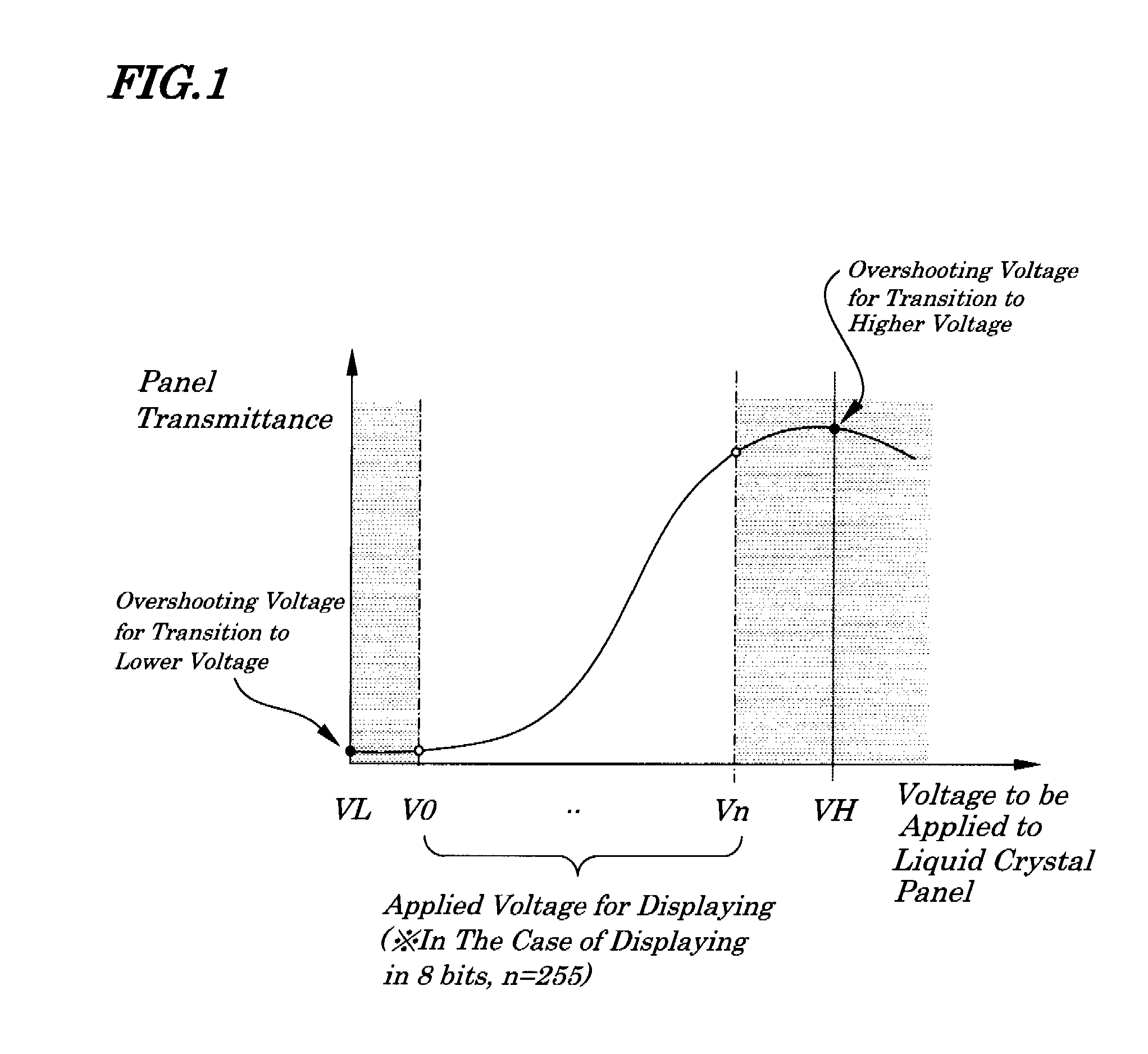
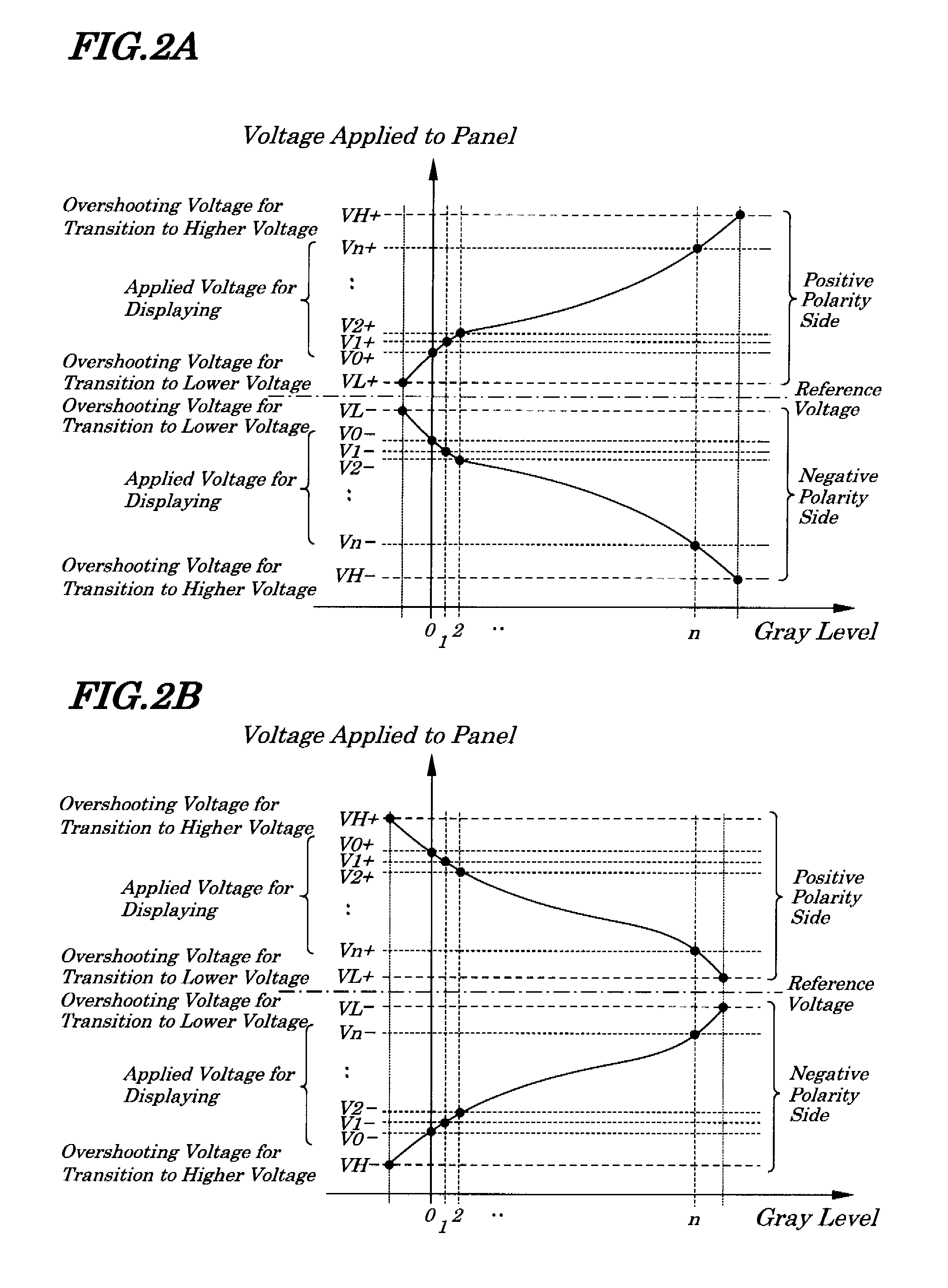
[0083]FIG. 1 is a diagram showing a method for driving a liquid crystal of a first embodiment of the present invention. FIGS. 2A and 2B are diagrams showing a relation between voltages applied to a liquid crystal panel and display gray level of the first embodiment. FIG. 3 is a diagram showing, as an example, a state of changes in voltages applied to a liquid crystal panel during a transition of gray level when voltages for displaying are different from one another in the method of driving the liquid crystal of the embodiment. FIG. 4 is a diagram explaining a relation between a gray-level value setting voltage and a source driver output voltage of the embodiment.

[0084]In the liquid crystal driving method, as shown in FIG. 1, in addition to voltages for displaying V0, . . . , Vn, as a voltage to be applied to a liquid crystal panel, an overshooting voltage VH for transition to a higher voltage is set in a voltage range being higher than a limit voltage Vn of the voltages for displayi...

second embodiment

[0095]FIG. 5 is a diagram showing a method for driving a liquid crystal panel according to the second embodiment of the present invention. In the method for driving a liquid crystal panel according to the second embodiment, as shown in FIG. 5, as a voltage to be applied to a liquid crystal panel, in addition to voltages for displaying V0, . . . , Vn, a voltage for overshooting driving for transition to a higher voltage is set in only the range of voltages being higher than an upper limit Vn in the range of the voltages for displaying and, when the voltage to be applied to the liquid crystal panel is changed to the maximum value Vn of the applied voltage for displaying, an overshooting driving operation using the voltage VH is performed. On the other hand, for example, the voltage V0-1 is used for displaying which is the lower limit of the applied displaying voltage and by which a displaying range is made narrow and an overshooting driving operation is performed by using the voltage ...

third embodiment

[0097]FIG. 6 is a diagram showing a method for driving a liquid crystal panel according to the third embodiment of the present invention. In the method for driving a liquid crystal panel according to the third embodiment, as shown in FIG. 6, as a voltage to be applied to a liquid crystal panel, in addition to voltages for displaying V0, . . . , Vn, a voltage VL for overshooting driving for transition to a lower voltage is set in only the range of voltages being higher than a lower limit V0 in the range of the voltages for displaying and, when the voltage to be applied to the liquid crystal panel is changed to the minimum value V0 of the applied displaying voltage, an overshooting driving operation using the voltage VL is performed. On the other hand, for example, the voltage Vn-1 is used for displaying which is an upper limit of the voltages for displaying and by which a displaying range is made narrow and an overshooting driving operation is performed by using the voltage Vn as the...


PUM


Abstract

A liquid crystal driving device is provided which enables an overshooting driving operation in transition among all gray levels. When a voltage for displaying is controlled so as to be a highest-level value out of the voltages for displaying corresponding to an input gray level range, an overshooting driving voltage for transition to a higher voltage which is added to a voltage side being higher than the highest-value value out of the voltages for displaying is applied to a liquid crystal panel and, when a voltage for displaying to be applied to the liquid crystal panel is controlled so as to be a lowest-level value out of the voltages for displaying corresponding to the input gray level range, an overshooting driving voltage for transition to a lower voltage which is added to a voltage side being lower than the lowest-level value of the voltages for displaying is applied to the liquid crystal panel.

Description

BACKGROUND OF THE INVENTION[0001]1. Field of the Invention[0002]The present invention relates to a liquid crystal driving device to drive a liquid crystal panel of a liquid crystal display device.[0003]The present application claims priority of Japanese Patent Application No. 2006-069691 filed on Mar. 14, 2006, which is hereby incorporated by reference.[0004]2. Description of the Related Art[0005]Conventionally, a liquid crystal display device has a problem of a phenomenon in which an image leaves a trail when moving images are displayed. This phenomenon is caused by a delay in response of a liquid crystal element. To prevent this phenomenon, so-called overshooting driving is used in which a voltage to be applied to a liquid crystal element making up a liquid crystal driving circuit is controlled so as to be a voltage being higher than an upper limit within a range of voltages to be applied when a still image is being displayed or a voltage being lower than a lower limit within the ...

Claims


Application Information

Patent Timeline
IPC IPC(8): G09G3/36
CPCG09G3/2011G09G3/3648G09G2320/103G09G2320/0257G09G2320/0252
Inventor KIMURA, HIROAKI
Owner NEC LCD TECH CORP
Why Eureka
Try Eureka