Micro-fluid ejecting device having embedded memory devices

a memory device and microfluid technology, applied in the field of ink jet printheads, can solve the problems of increasing the cost of printing head production, increasing the complexity of printheads, and increasing so as to increase the area of substrates required for memory device allocation, increase the effect of on-board memory and reduce the area of substrates

Inactive Publication Date: 2007-09-20
SLINGSHOT PRINTING LLC
View PDF23 Cites 3 Cited by
  • Summary
  • Abstract
  • Description
  • Claims
  • Application Information

AI Technical Summary

Benefits of technology

[0006] An advantage of the invention is that it provides printheads having increased on-board memory while reducing the area of the substrate required for memory device allocation. For example, printheads having conventional fuse or fuse diode memory devices require about four times the substrate surface area as an embedded memory device according to the invention. Accordingly, for the same substrate surface area, substantially more memory can be provided for a printhead using an embedded memory device according to the invention. Likewise, printhead substrates according to the invention containing the same amount of memory as substrates containing fuse memory devices, can be made substantially smaller.
[0007] For purposes of this invention, the term “embedded” is intended to mean integral with the substrate as opposed to being separate from but physically connected to the substrate by wires and / or electrical traces. An embedded memory device is a device that is formed in the silicon substrate that is used for providing the fluid ejection devices and drivers for a micro-fluid ejecting device such as an ink jet printhead.

Problems solved by technology

As the capabilities of ink jet printers are increased to provide higher quality images at increased printing rates, printheads, which are the primary printing components of ink jet printers, continue to evolve and become more complex.
As the complexity of the printheads increases, so does the cost for producing the printheads.

Method used


Image

  • Micro-fluid ejecting device having embedded memory devices
  • Micro-fluid ejecting device having embedded memory devices
  • Micro-fluid ejecting device having embedded memory devices

Examples


Embodiment Construction

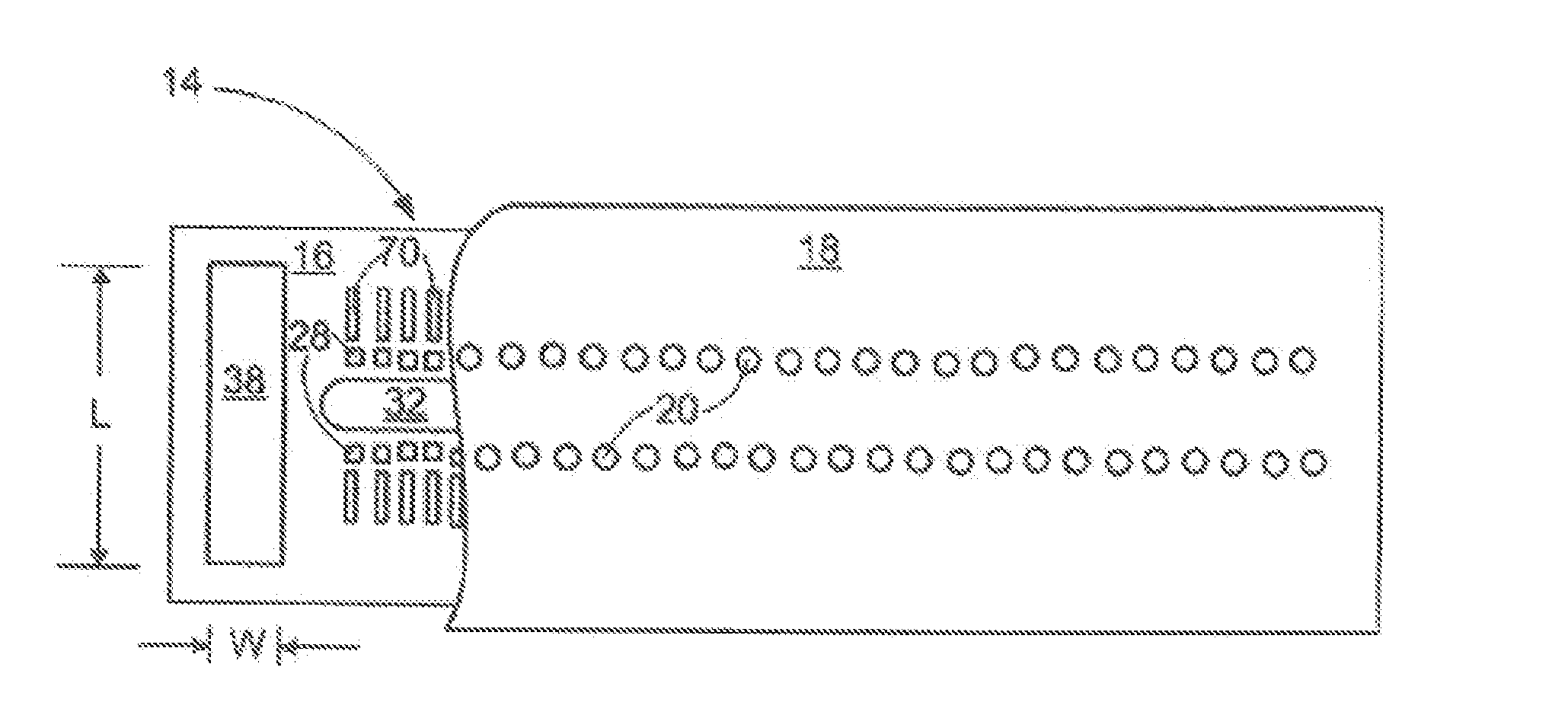
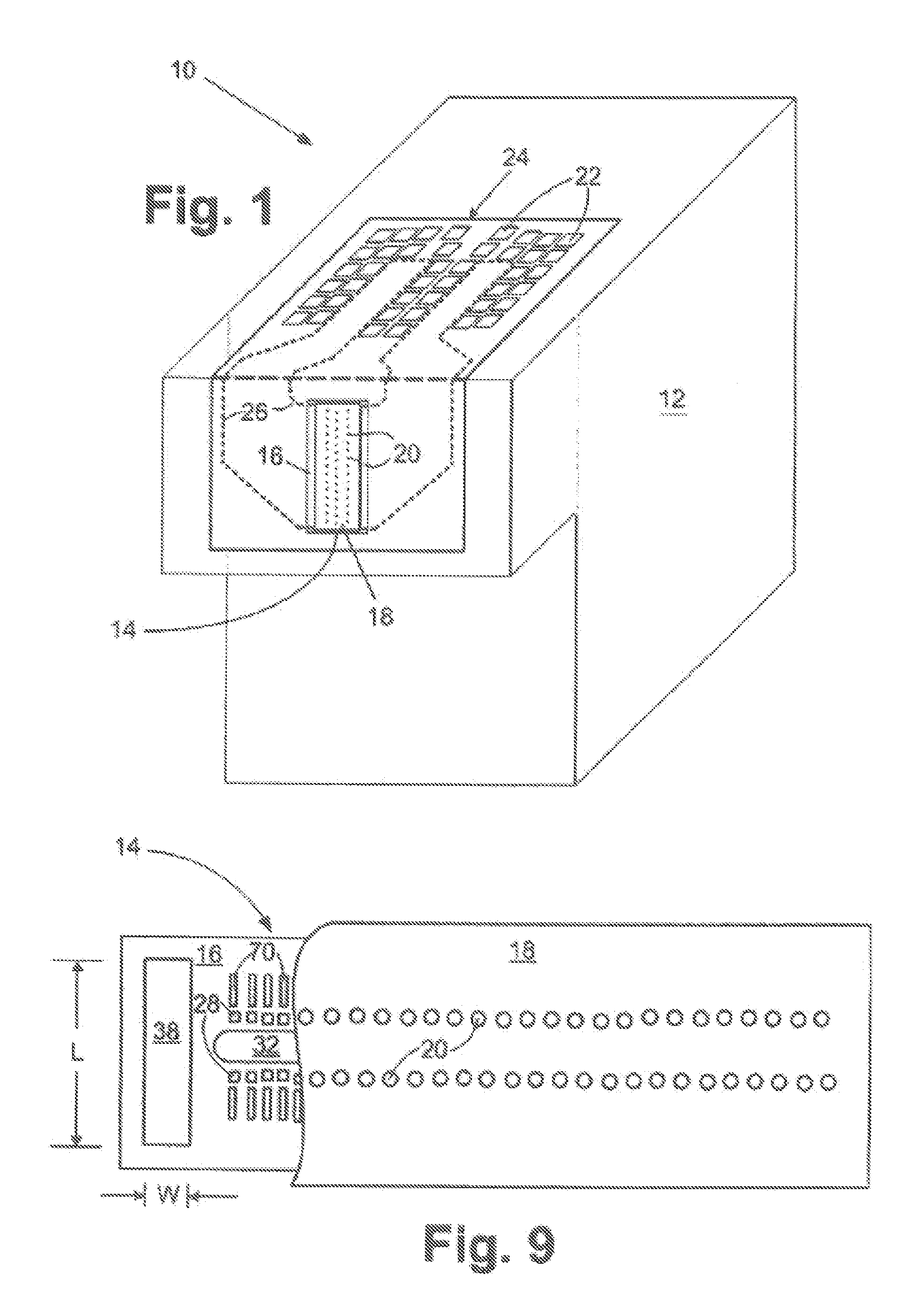
[0018] With reference to FIG. 1, a fluid cartridge 10 for a micro-fluid ejecting device is illustrated. The cartridge 10 includes a cartridge body 12 for supplying a fluid to a fluid ejection head 14. The fluid may be contained in a storage area in the cartridge body 12 or may be supplied from a remote source to the cartridge body.

[0019] The fluid ejection head 14 includes a semiconductor substrate 16 and a nozzle plate 18 containing nozzle holes 20. It is preferred that the cartridge be removably attached to a micro-fluid ejecting device such as an ink jet printer. Accordingly, electrical contacts 22 are provided on a flexible circuit 24 for electrical connection to the micro-fluid ejecting device. The flexible circuit 24 includes electrical traces 26 that are connected to the substrate 16 of the fluid ejection head.

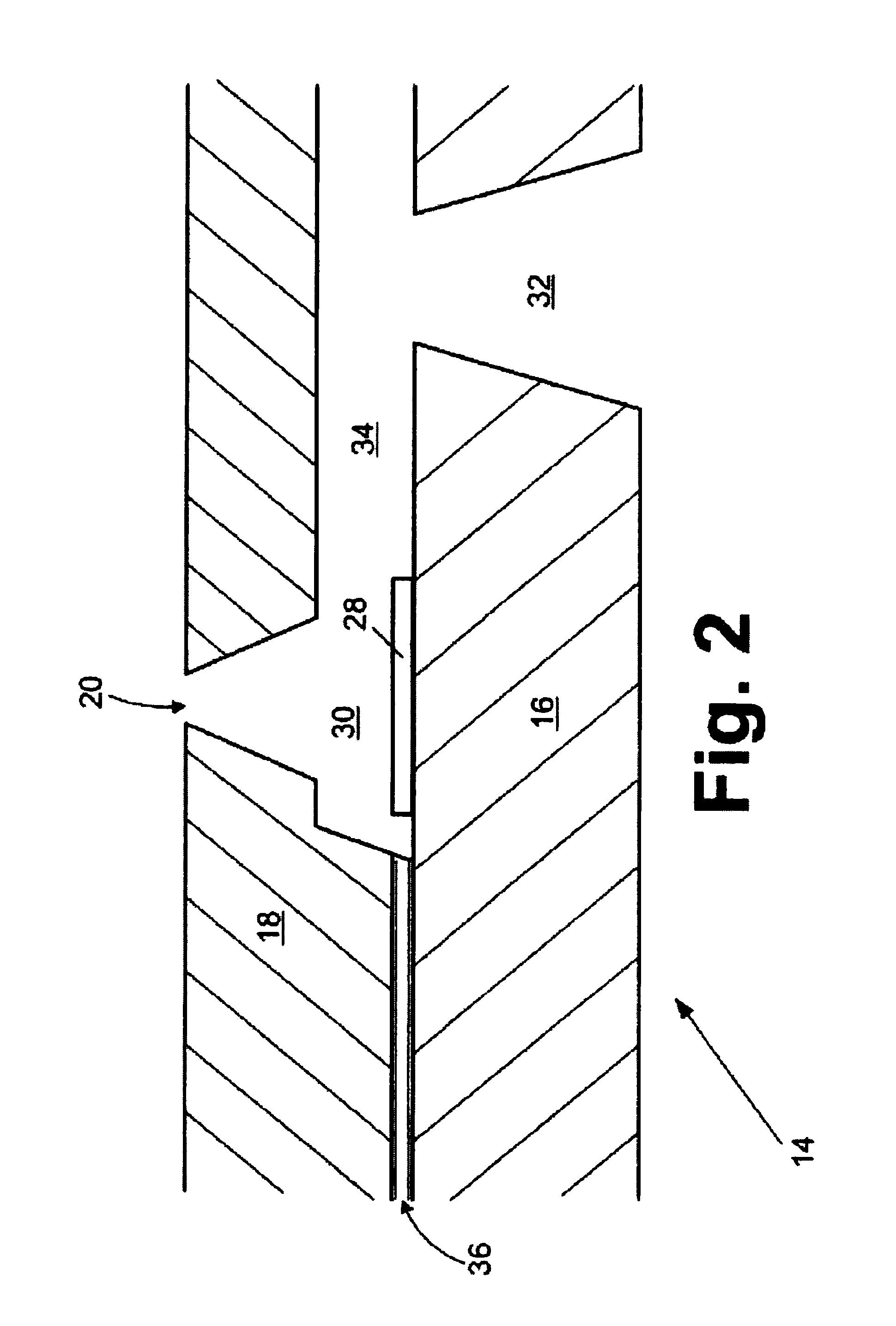
[0020] An enlarged view, not to scale, of a portion of the fluid ejection head 14 is illustrated in FIG. 2. In this case, the fluid ejection head 14 contains a therma...


PUM


Abstract

A micro-fluid ejecting device includes a semiconductor substrate, a plurality of fluid ejection elements formed on the semiconductor substrate, and a plurality of nonvolatile programmable memory devices for storing information related to the operation of the micro-fluid ejecting device. The programmable memory devices, which are at least partially embedded in the semiconductor substrate, each include a source region and a drain region formed in the semiconductor substrate. The source and drain regions have a conductivity type which is opposite the conductivity type of the semiconductor substrate. An insulative layer is formed on the semiconductor substrate over the source region and drain region. A floating gate region is formed on the insulative layer and is spatially disposed between the source region and drain region. The floating gate region is electrically insulated from the source and drain regions by the insulative layer. Electrical contacts are connected to the source region and the drain region. The programmable memory devices collectively provide a high density of memory bits embedded on the substrate for storing information about the micro-fluid ejecting device.

Description

[0001] This application claims priority as a continuation of co-pending U.S. patent application Ser. No. 10 / 706,457 filed Nov. 12, 2003.FIELD OF THE INVENTION [0002] The invention relates to ink jet printheads and in particular to ink jet printheads containing memory devices embedded in a printhead substrate. BACKGROUND OF THE INVENTION [0003] Ink jet printers continue to experience wide acceptance as economical replacements for laser printers. Such ink jet printers are typically more versatile than laser printers for some applications. As the capabilities of ink jet printers are increased to provide higher quality images at increased printing rates, printheads, which are the primary printing components of ink jet printers, continue to evolve and become more complex. As the complexity of the printheads increases, so does the cost for producing the printheads. Nevertheless, there continues to be a need for printers having enhanced capabilities. For example, ink cartridges having memo...

Claims


Application Information

Patent Timeline
Patent Type & Authority Applications(United States)
IPC IPC(8): B41J2/05B41J2/14
CPCB41J2/04541B41J2/0458B41J2/04581B41J2202/17B41J2/14201B41J2202/13B41J2/14016
Inventor EDELEN, JOHN G.PARISH, GEORGE K.ROWE, KRISTI M.
Owner SLINGSHOT PRINTING LLC
Why Eureka
Try Eureka