Insertion type fuse with breakage indication

a technology of insertion type and indication, which is applied in the direction of electrical equipment, instruments, alarms, etc., can solve the problems of long repair work time, inconvenient installation of car parts, and inability to form easily overcurrent current, so as to achieve the effect of reducing cost and increasing production ra

Active Publication Date: 2007-09-20
HANSOR POLYMER TECH CORP
View PDF3 Cites 5 Cited by
  • Summary
  • Abstract
  • Description
  • Claims
  • Application Information

AI Technical Summary

Benefits of technology

[0006] Accordingly, the primary object of the present invention is to provide an insertion type fuse with breakage indication, wherein a bi-directional SMD LED set is used s

Problems solved by technology

However the prior art bulb easily burns so that the current with over-current can no be formed easily.
Thus the repair work needs a long time.
Thereby the bulb in the prior art is protruded from the conventional fuse structure so that it is not suitable to be installed within a car.
A disa

Method used


Image

  • Insertion type fuse with breakage indication
  • Insertion type fuse with breakage indication
  • Insertion type fuse with breakage indication

Examples


Embodiment Construction

[0017] In order that those skilled in the art can further understand the present invention, a description will be described in the following in details. However, these descriptions and the appended drawings are only used to cause those skilled in the art to understand the objects, features, and characteristics of the present invention, but not to be used to confine the scope and spirit of the present invention defined in the appended claims.

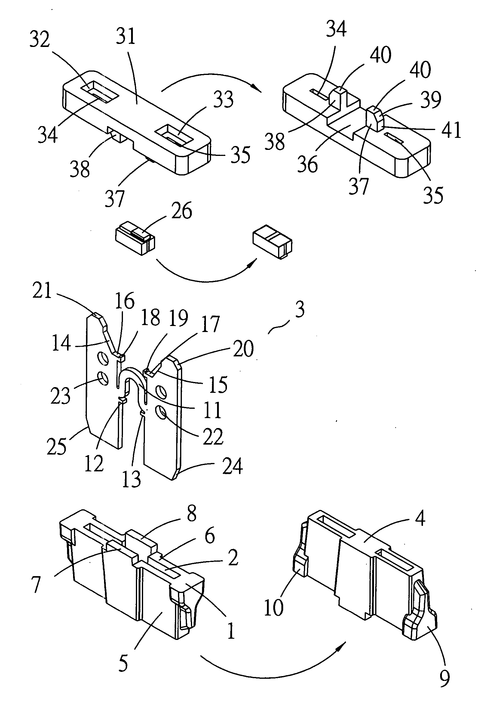
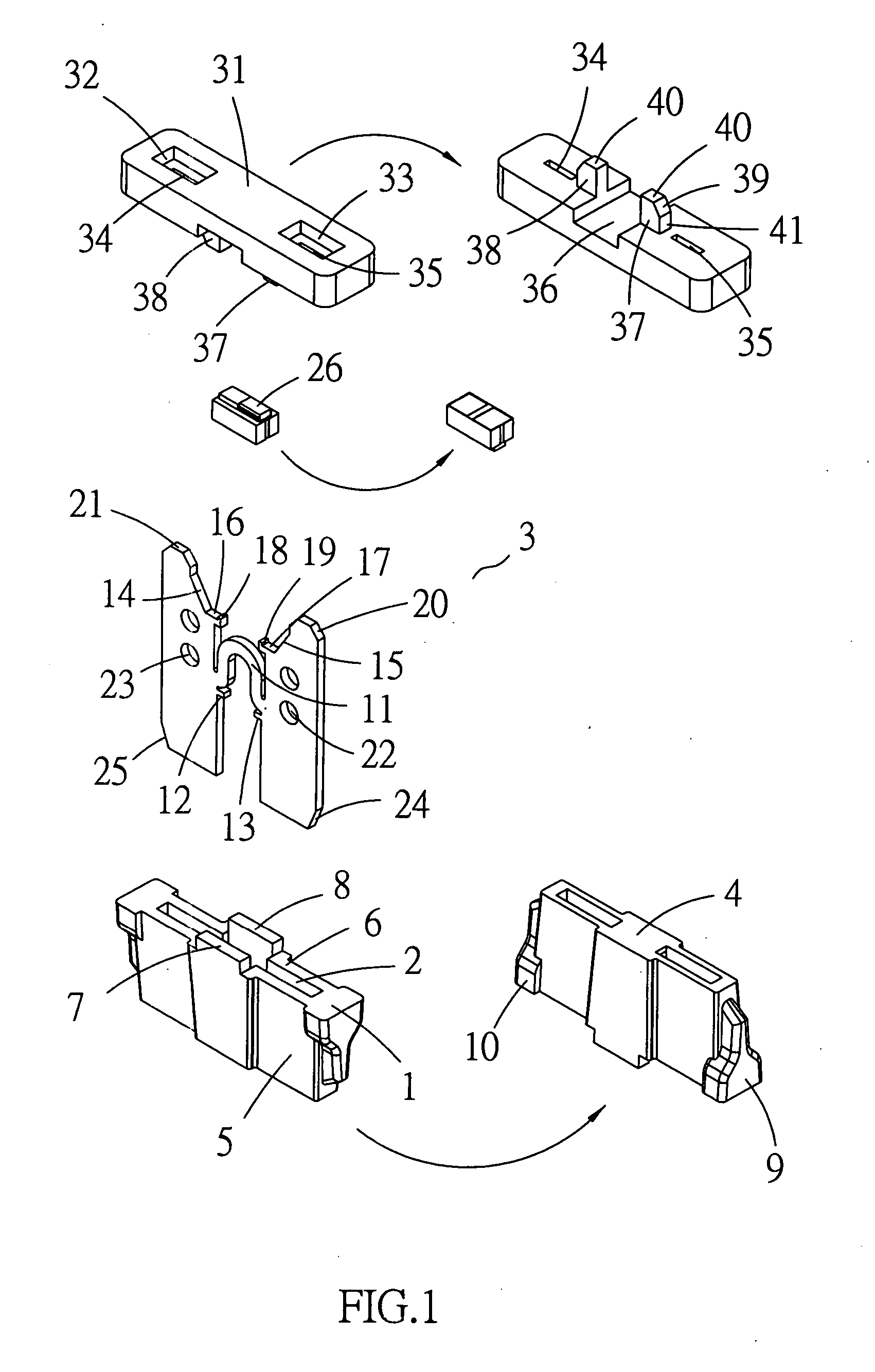
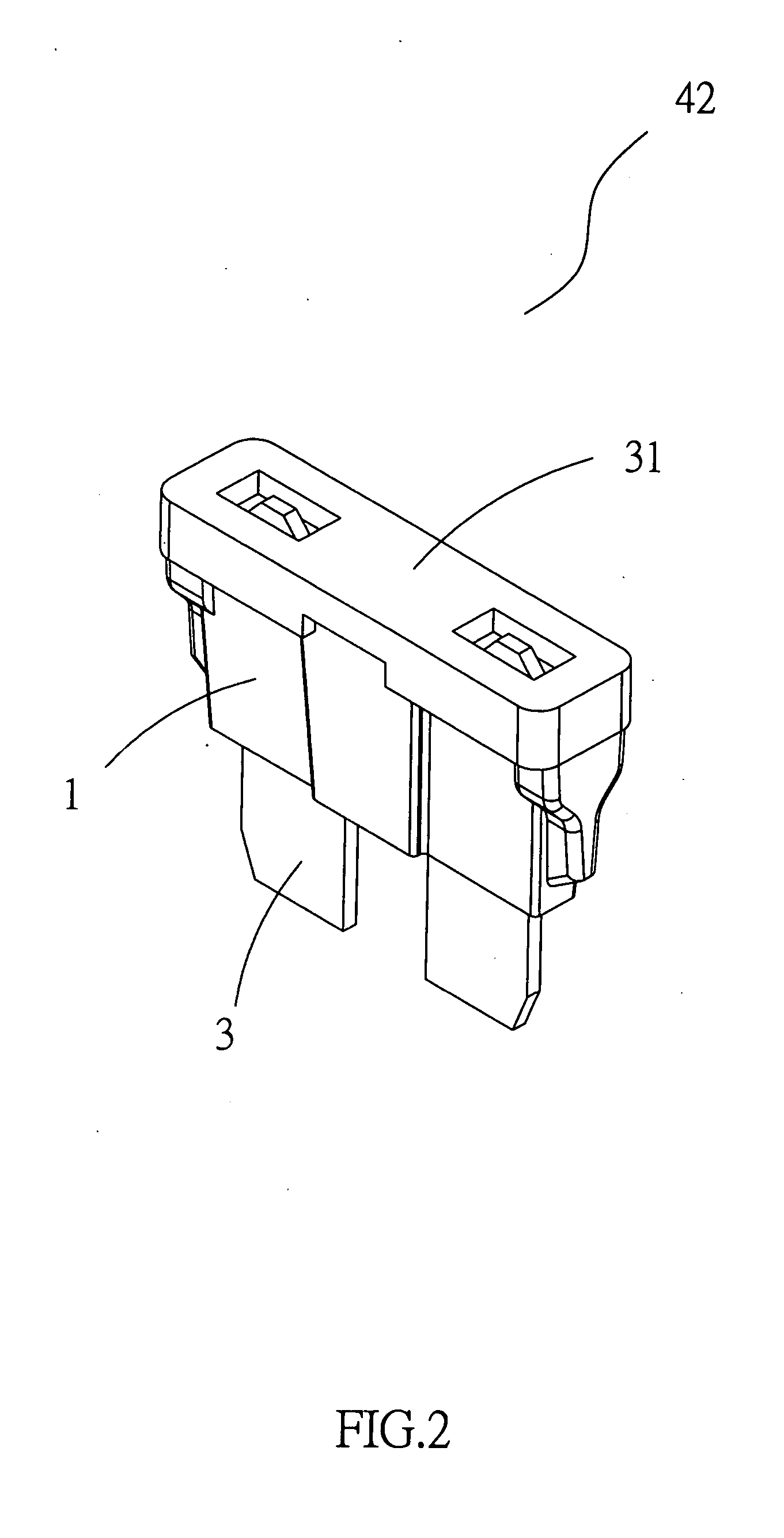
[0018] Referring to FIGS. 1 and 2, the inserting fuse with a break indication of the present invention is illustrated. The present invention has the following elements.

[0019] A seat 1 has a long receiving chamber 2 for receiving a metal fuse 3. A middle section of the long receiving chamber 2 is wider and two ends of the long receiving chamber 2 are narrow. Two opposite sides of the seat 1 are two protecting plates 5 and 6. Each protecting plate has a rectangular ear 7, 8 at an upper middle section thereof. Another two opposite sides of the sea...


PUM


Abstract

An insertion type fuse with breakage indication comprises a seat having a long receiving chamber for receiving a metal fuse; an rectangular bi-directional SMD form LED set being located on the buckle portions; the LED set being a coating device and being high temperature tolerant; the LED set being connected to a circuit; the LED including two LEDs and being serially connected with a voltage divided resistor; a fuse wire being connected between the LED set and a load; the LED set being buckled to the buckle portions; when the fuse wire breaks, light will emit out so as to show that the fuse wire breaks; thereby a break fuse can be fined rapidly. In assembly, the seat and the cover are integrally formed. The LED set is adhered to the metal fuse and then the metal fuse is assembled into the long receiving chamber.

Description

FIELD OF THE INVENTION [0001] The present invention relates to an insertion type fuse with breakage indication, wherein a bi-directional SMD LED set is used so that the fuse can be used bi-directionally. The assembly of the present invention is easy and can be produced automatically with higher production rate and lower cost. BACKGROUND OF THE INVENTION [0002] In the prior art fuse, a small bulb is connected between two metal electrodes. The bulb has a larger resistor which is greater than that of the fuse so that current only flows through the fuse instead of the bulb. Thus the bulb will not light up. When the fuse breaks due to overload, the current flows through the bulb so that the bulb will light-up. However the prior art bulb easily burns so that the current with over-current can no be formed easily. Thus the repair work needs a long time. Thereby the bulb in the prior art is protruded from the conventional fuse structure so that it is not suitable to be installed within a car...

Claims


Application Information

Patent Timeline
IPC IPC(8): H02H5/04
CPCH01H85/32
Inventor HUANG, JUNG-SHENG
Owner HANSOR POLYMER TECH CORP
Why Eureka
Try Eureka