
Protection device: surge suppressing conductor

a protection device and conductor technology, applied in the direction of resistors, emergency protection arrangements for limiting excess voltage/current, non-adjustable resistors, etc., can solve the problem of not designed to slow down the steep impulse front, and achieve the effect of enhancing the effectiveness and low cos

Inactive Publication Date: 2007-09-20
RIZK FAROUK A M +1
View PDF22 Cites 5 Cited by
  • Summary
  • Abstract
  • Description
  • Claims
  • Application Information

AI Technical Summary

Benefits of technology

[0006]To provide a low cost compliment to the existing surge protection systems for electrical transmission and distribution lines and substations and to enhance their effectiveness.
[0007]To provide a low cost surge protection system that can be mounted directly onto any electrical transmission / distribution line.

Problems solved by technology

They are not designed to slow down the steep impulse front.

Method used


Image

  • Protection device: surge suppressing conductor
  • Protection device: surge suppressing conductor
  • Protection device: surge suppressing conductor

Examples


Embodiment Construction

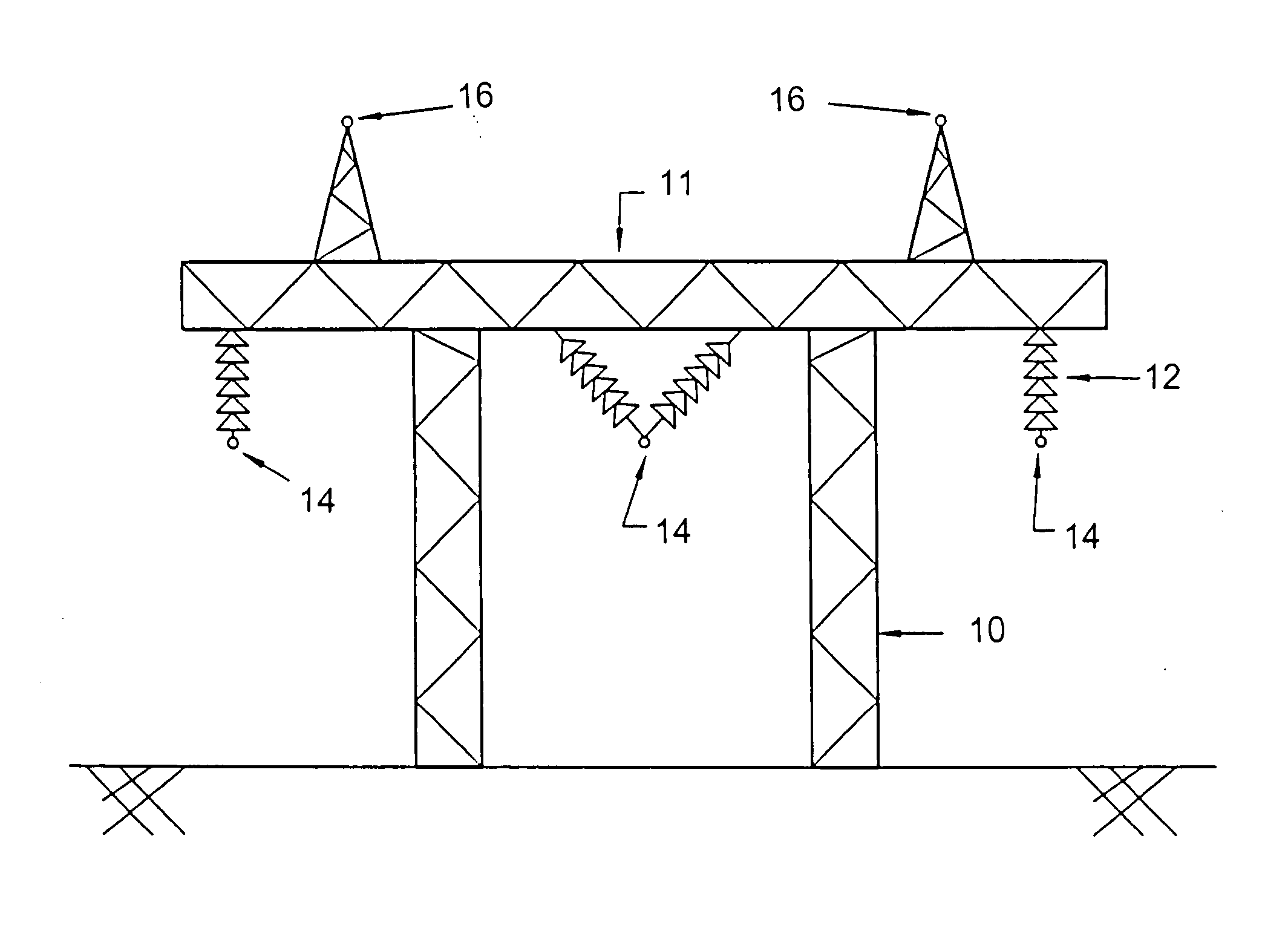
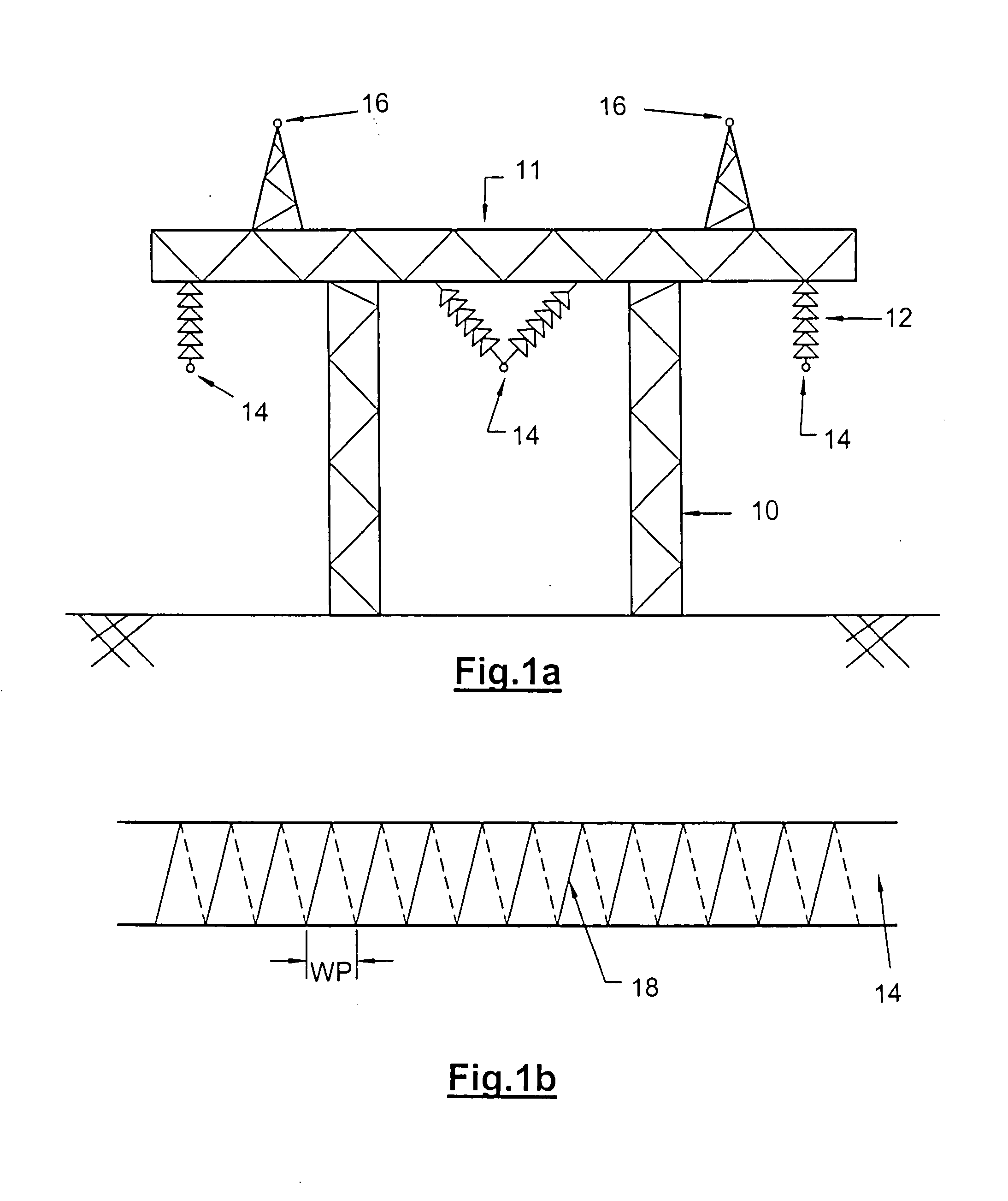
[0034]Referring to FIG. 1a, there a shown a part of an electrical transmission network having a tower 10, a portal 11, insulating strings 12, power conductors 14 and an overhead ground wires 16, wherein the present invention may be used.

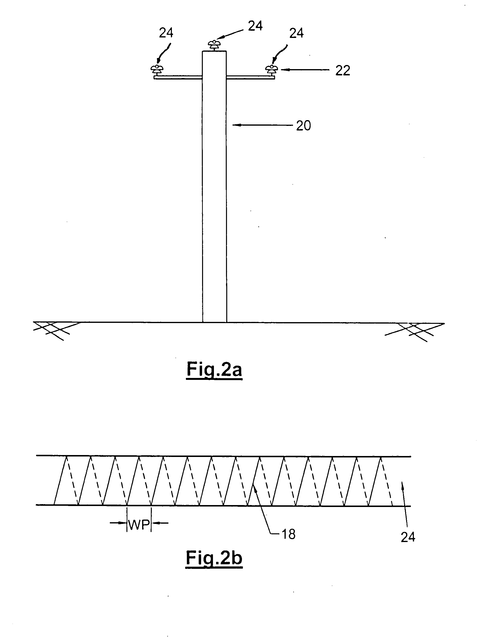
[0035]Referring to FIG. 1b, the power conductors 14 and overhead ground wires 16 (shown in FIG. 1a), which are more generally termed electrical conductor lines, are fitted with a wet / dry glow-based surge suppressing coil, according to a preferred embodiment of the present invention. The coil is made of pulse-less corona producing conductors 18 wound around the electrical conductor line. Each pulse-less corona producing conductor 18 has a diameter not exceeding 0.1 mm for reducing a corona inception voltage of the electrical conductor line upon which each conductor is wound, in both dry and wet conditions. The conductors 18 or the like may be wound around a live power conductor 14 at a given winding pitch defining a winding pitch distance WP.

[0036]In ...


PUM


Abstract

A lightning protection or internal surge device designed to suppress surges on electrical transmission or distribution lines by expending some of the excess energy in the form of corona discharge in both wet and dry conditions. The device is a very thin (of diameter not exceeding 0.1 mm) conducting wire, fiber, filament, or a bundle of such filaments, or a yarn or woven or knitted fabric made of such fibers or wires which is wound around a live conductor or ground wire forming a coil. When the coil is exposed to the fields created by the voltage surges on the line or ground wire it enhances corona losses on the line thereby damping / suppressing the surges as well as prolonging the front time of the surge to reduce its steepness.

Description

FIELD OF THE INVENTION[0001]The present invention relates to a lightning protection device.BACKGROUND OF THE INVENTION[0002]When an electrical conductor is struck by lightning, current and associated voltage waves travel in opposite directions along the lines towards terminal substations. These voltage waves are generally characterized by steep fronts and high amplitudes. The amplitude of the impinging wave is eventually limited by a lightning arrester. The steepness of the impinging wave on the other hand is practically determined by the corona characteristics of the line and the travel distance from the strike point to the substation and is not influenced by the arrester.[0003]For a given distance between the arrester and protected equipment, the maximum steepness determines the necessary protection margin above the arrester protective level. Furthermore for insulated windings a steep impulse generally leads to unfavourable voltage stress of the insulation.[0004]It is to be noted ...

Claims


Application Information

Patent Timeline
Patent Type & Authority Applications(United States)
IPC IPC(8): H02H9/06
CPCH02G7/22H02G13/80H02G13/00
Inventor RIZK, FAROUK A.M.RIZK, AMR
Owner RIZK FAROUK A M
Learn More