
Pin with spherical lead-in portion

a technology of lead-in portion and pin, which is applied in the direction of yielding coupling, coupling, fastening means, etc., can solve the problems of increasing the difficulty of assembling the pin into the hole, affecting the assembly efficiency of the pin, so as to reduce the assembly difficulty, facilitate the entry, and increase the lead length

Inactive Publication Date: 2007-09-20
DEERE & CO
View PDF11 Cites 0 Cited by
  • Summary
  • Abstract
  • Description
  • Claims
  • Application Information

AI Technical Summary

Benefits of technology

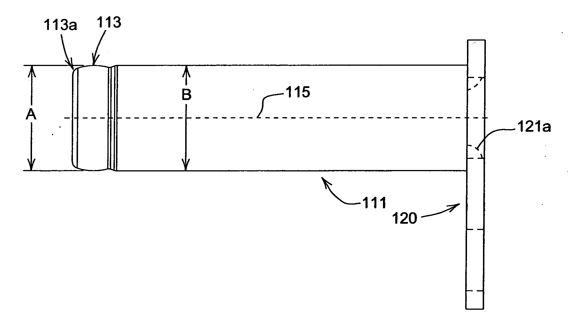
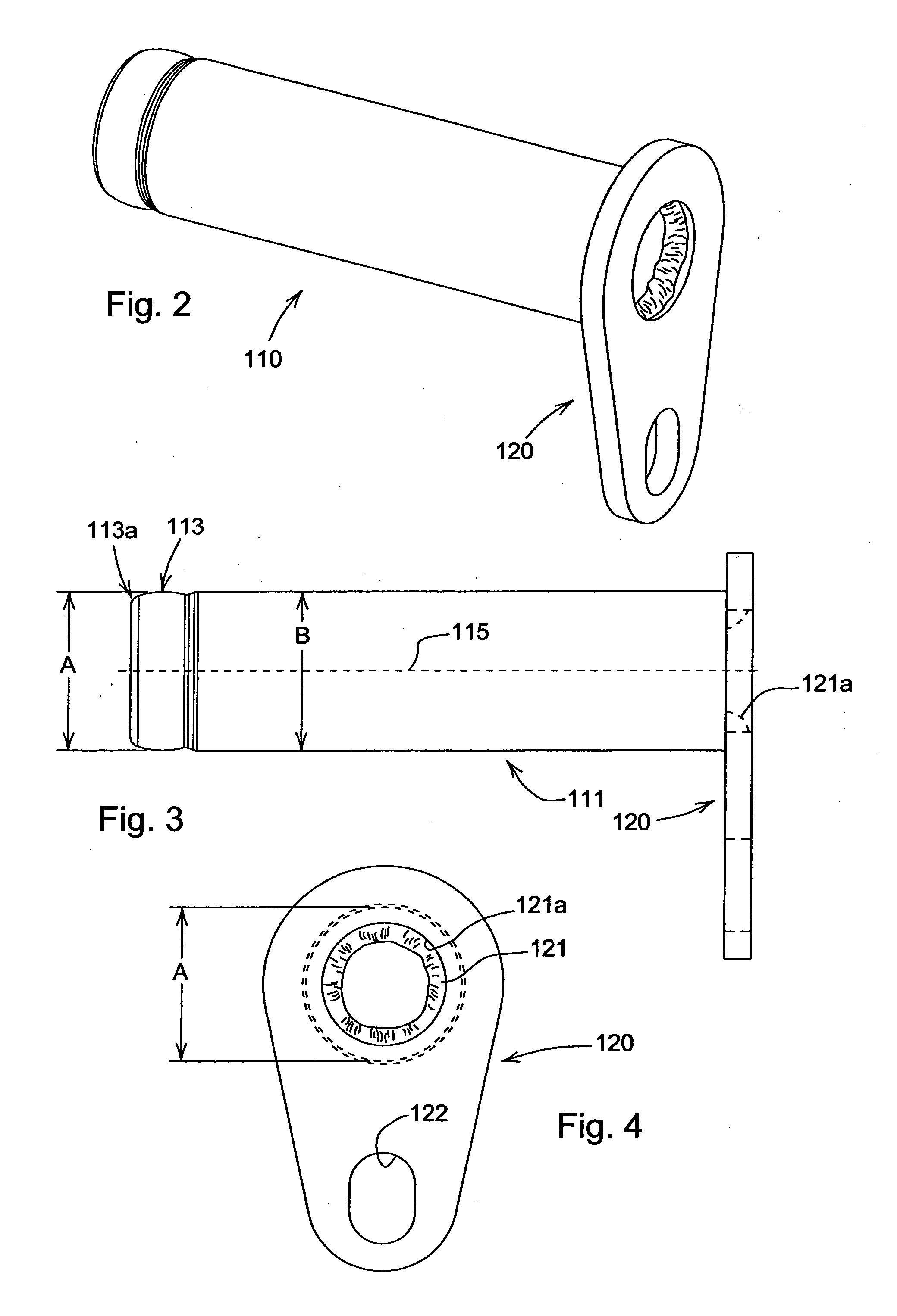
[0004] Described and claimed herein is an invention that significantly reduces the assembly difficulties associated with the conventional pins described above. The invention includes a pin with a spherical diameter at its free end. The spherical diameter, which is sized to be equal to or slightly smaller than the cylindrical diameter of the hole is placed in the hole and advanced in the hole for a lead in length that is significantly greater than that of the conventional pin. This is possible because opposite sides of the spherical diameter are always slightly less than or equal to the cylindrical diameter of the hole. Once the greater lead in length is attained, a chamfer on the pin eases the entry of the pin into the hole because centering the pin in the hole at the chamfer effectively aligns the centerlines of the pin and the hole.

Problems solved by technology

The installation of a conventional pin into a matching bore, bushing or seal without damaging the same is relatively difficult as the mating chamfers merely move the free end of the pin toward the center of the hole; the chamfers do not align the centerlines of the pin and the hole.
Thus, as the difference between the diameters of the pin and the hole becomes smaller, the difficulties of assembling the pin into the hole become greater and the angle of entry for the pin must more precisely match the angle of the centerline of the hole.
These difficulties arise due to the fact that the lead in length, i.e., the total possible length of the pin entering the hole prior to total alignment of the centerlines is generally no greater than the length of the chamfer.
Also, seals and composite bushings may also be damaged when entry of the pin is forced.
This leads to unnecessary assembly delays and frustrations.

Method used


Image

  • Pin with spherical lead-in portion
  • Pin with spherical lead-in portion
  • Pin with spherical lead-in portion

Examples


Embodiment Construction

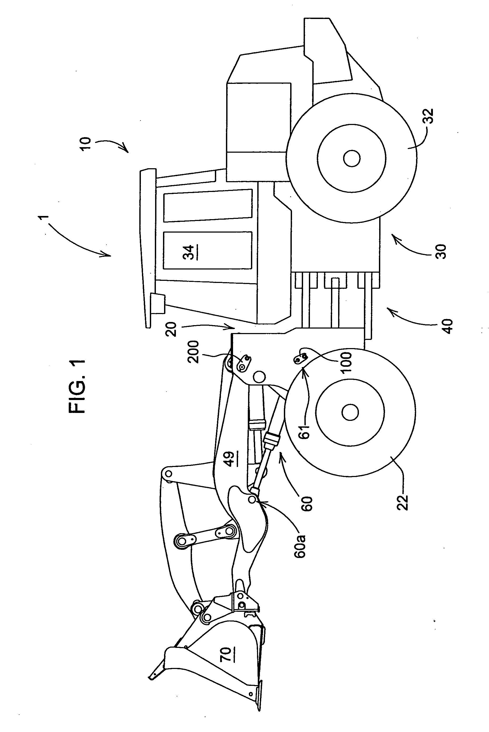
[0019]FIG. 1 is a side view of an exemplary embodiment of a work vehicle employing the invention. The particular work vehicle illustrated in FIG. 1 is a loader 1 and it includes a frame 10 which includes a cab 34, a front frame portion 20, a rear frame portion 30, front wheels 22, rear wheels 32, a work tool 70, a boom 49 and a hydraulic cylinder 60 pivotally connected to the front frame portion 20 at pivot point 61 and pivotally connected to the boom at pivot point 60a. The front and rear wheels 22 and 32 propel the work vehicle 1 along the ground in a manner well known in the art.

[0020] Pin units 100 and 200 (e.g., flagged pin units) are exemplary embodiments of the invention. While pins 100 and 200 are both exemplary embodiments of the invention, only pin 100 will be addressed hereafter as it is identical to pin 200 and additional wording addressing pin 200 would be redundant.

[0021]FIG. 2 is an oblique view of an exemplary embodiment of the invention illustrated as pin 100 in F...


PUM


Abstract

A pin has a shank with a spherical lead-in portion at the free end thereof. The spherical lead-in portion has a diameter that is equal to or slightly less than the diameter of a cylindrical portion of the pin. The purpose of the spherical lead-in portion is to allow a greater portion of the pin to enter a matching hole before further alignment of the centerlines of the pin and the hole is required. This makes aligning the centerlines significantly easier and reduces wear on the structure defining the matching hole. A relief portion following the spherical lead-in portion as well as a chamfer following the relief portion aid in the final alignment.

Description

FIELD OF THE INVENTION [0001] The invention relates to pins typically used in pivoting mechanisms for off road work vehicles. More specifically, it relates to a method and device for allowing greater variation in the angle of pins as they are assembled into mating holes. BACKGROUND OF THE INVENTION [0002] Pins have, traditionally, been designed as one-piece cylindrical rods or pins integrated with pin retainers. Conventional pin retainers have attachment areas suitable for attaching the entire pin to a part after the one-piece cylindrical pin has been assembled to a mating hole. Conventional pins include only a chamfer at the free end to ease their entry into the mating holes. Typically, the mating hole, also has a chamfer to ease the entry of the free end of the pin. SUMMARY OF THE INVENTION [0003] The installation of a conventional pin into a matching bore, bushing or seal without damaging the same is relatively difficult as the mating chamfers merely move the free end of the pin ...

Claims


Application Information

Patent Timeline
Patent Type & Authority Applications(United States)
IPC IPC(8): F16B21/00
CPCY10T403/32983F16B19/02
Inventor FAITH, ROBERT MARTINDITZLER, STEVEN JAY
Owner DEERE & CO
Learn More