
Multi-layered type electrochemistry cell of improved safety

a multi-layered type, electrochemical cell technology, applied in the direction of cell components, flat cell grouping, sustainable manufacturing/processing, etc., can solve the problems of low utilizability, troublesome, complicated and troublesome stacking type electrochemical cell, etc., to maintain the structural stability of the electrochemical cell

Active Publication Date: 2007-09-20
LG ENERGY SOLUTION LTD
View PDF14 Cites 47 Cited by
  • Summary
  • Abstract
  • Description
  • Claims
  • Application Information

AI Technical Summary

Benefits of technology

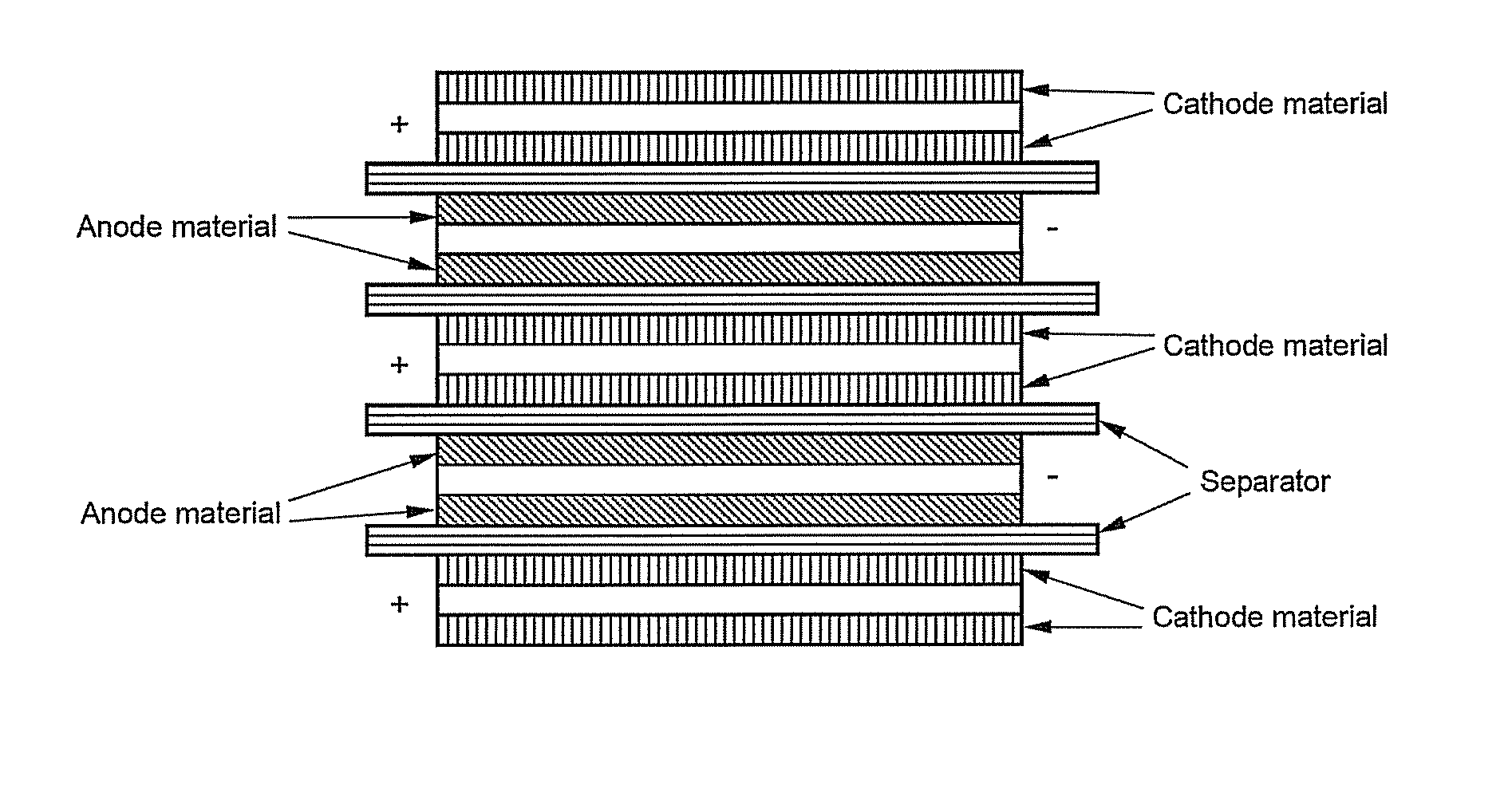
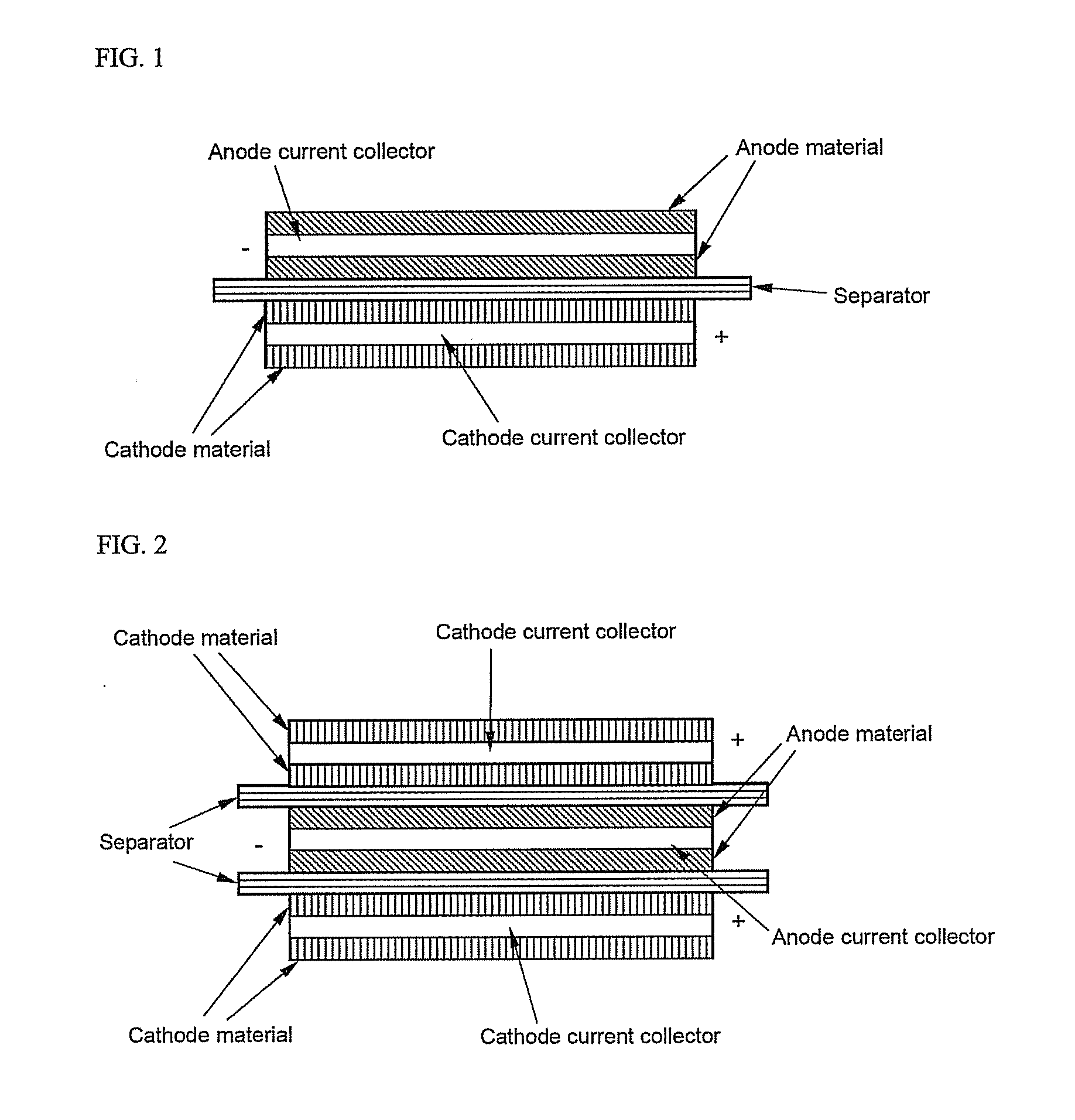
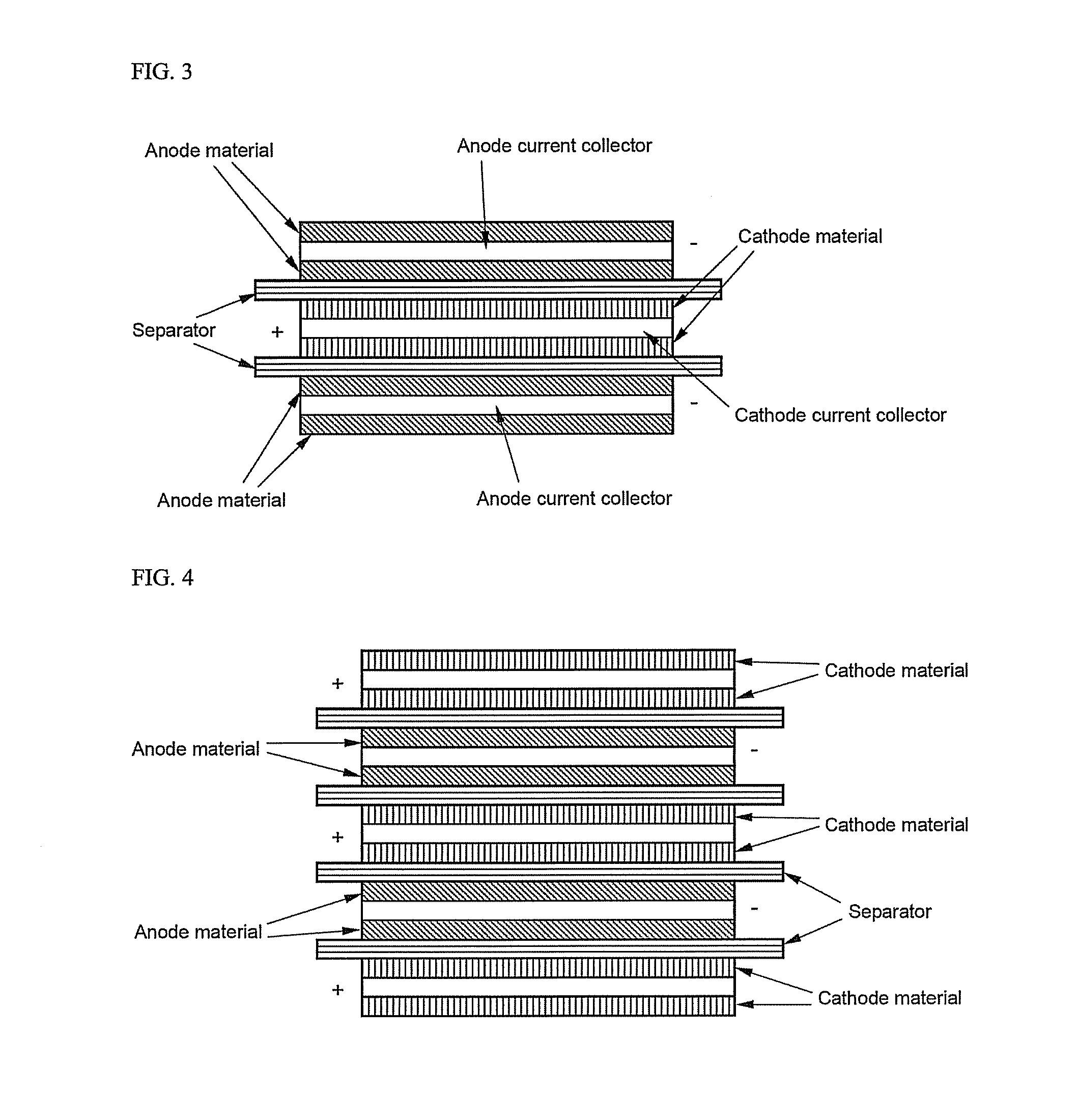
[0008]As a result of a variety of extensive and intensive studies and experiments to solve the problems as described above, the inventors of the present invention have found that, when separators of a plurality of unit cells folded by a separation film formed in the shape of a long sheet are secured to the separation film by thermal welding, the electrodes of the stacked electrodes are prevented from being separated from the separation film or from being twisted due to external impacts and vibrations, whereby the electrochemical cell is restrained from generating heat or catching fire, and the structural stability of the electrochemical cell is maintained even when the temperature of the electrochemical cell is increased, or the volume of the electrochemical cell is increased due to the generation of gas. The present invention has been completed based on these findings.

Problems solved by technology

The jelly-roll type electrochemical cell is suitable for cylindrical batteries; however, the jelly-roll type electrochemical cell is not suitable for prismatic batteries or pouch-shaped batteries because the electrode active material may be detached, and the spatial utilizability is low.
The stacking type electrochemical cell has an advantage in that the stacking type electrochemical cell can be constructed in a prismatic structure; however, the stacking type electrochemical cell has disadvantages in that a process for manufacturing the stacking type electrochemical cell is complicated and troublesome, and, when external impacts are applied to the stacking type electrochemical cell, electrodes of the stacking type electrochemical cell are pushed with the result that short circuits occur in the stacking type electrochemical cell.
In the electrochemical cell having the above-described structure, however, the long separation film is used with the result that the electrodes of the unit cells may be separated from the separation film or the electrodes of the unit cells may be twisted due to impacts and vibrations applied to the outside and the inside of the battery, which may cause the occurrence of short circuits in the secondary battery.
According to circumstances, the secondary battery may catch fire or explode.

Method used


Image

  • Multi-layered type electrochemistry cell of improved safety
  • Multi-layered type electrochemistry cell of improved safety
  • Multi-layered type electrochemistry cell of improved safety

Examples


example 1

[0037]A cathode mixture slurry was prepared by adding 95 weight percent of LiCoO2 as a cathode active material, 2.5 weight percent of Super-P (a conducting agent), and 2.5 weight percent of PVdf (a coupling agent) to N-methyl-2-pyrrolidone (NMP) as a solvent. An anode mixture slurry was prepared by adding 95 weight percent of artificial graphite as an anode active material, 2.5 weight percent of Super-P (a conducting agent), and 2.5 weight percent of PVdf (a coupling agent) to NMP as a solvent. The cathode mixture slurry and the anode mixture slurry were coated on an aluminum foil and a copper foil, respectively. Subsequently, the aluminum foil and the copper foil were dried and pressed. In this way, cathodes and anodes were manufactured.

[0038]Cell Guard™ was used as separators. The cathodes, the anodes, and the separators were sequentially stacked one on another to construct bicells. The same material as the separators, i.e., Cell Guard™, was also used as a separation film. A total...

example 2

[0039]A battery was completed in the same manner as Example 1 except that the separators were thermally welded to the separation film at the lower ends of the bicells.

experimental example 1

[0041]The batteries manufactured according to the Examples and the Comparative Examples were charged to 4.2 V, and then the batteries were dropped from the height of 1 m. The dropping experiments were carried out 50 times in succession. The results of the dropping experiments are indicated in Table 1 below.

TABLE 1Number of batteriesshort-circuited during50 continuous droppingNumber of batteriesexperimentsExample 11002Example 210010Comparative Example 110085

[0042]It can be seen from Table 1 that the occurrence of short circuits was considerably reduced even after the 50 continuous dropping experiments were carried out for the batteries including electrochemical cells constructed in a structure in which a plurality of unit cells are folded by a separation film formed in the shape of a long sheet, and separators of the unit cells are secured to the separation film by thermal welding.


PUM

PropertyMeasurementUnit
temperatureaaaaaaaaaa
heightaaaaaaaaaa

Abstract

Disclosed herein is an electrochemical cell constructed in a structure in which a plurality of full cells or bicells, as unit cells, are folded by a separation film formed in the shape of a long sheet, and separators of the unit cells are secured to the separation film by thermal welding. The electrochemical cell according to the present invention has the effect of preventing the electrodes of the stacked electrodes from being separated from the separation film or from being twisted due to external impacts and vibrations, thereby restraining the electrochemical cell from generating heat or catching fire. Furthermore, the structural stability of the electrochemical cell is maintained even when the temperature of the electrochemical cell is increased, or the volume of the electrochemical cell is increased due to the generation of gas.

Description

FIELD OF THE INVENTION[0001]The present invention relates to a multi-layered type electrochemical cell having improved safety, and, more particularly, to an electrochemical cell constructed in a structure in which a plurality of full cells or bicells, as unit cells, are folded by a separation film formed in the shape of a long sheet, and separators of the unit cells are secured to the separation film by thermal welding.BACKGROUND OF THE INVENTION[0002]As mobile devices have been increasingly developed, and the demand of such mobile devices has increased, the demand of secondary batteries has also sharply increased. Among them is a lithium secondary battery having high energy density and voltage and excellent preservation and service-life characteristics, which has been widely used as an energy source for various electronic products as well as the mobile devices.[0003]Based on their external and internal structures, the secondary batteries are generally classified into a cylindrical ...

Claims


Application Information

Patent Timeline
Patent Type & Authority Applications(United States)
IPC IPC(8): H01M10/04H01M2/18
CPCH01M10/052H01M10/0525H01M10/0583H01M2/18H01M10/0587Y02E60/122H01M10/0585Y02E60/10Y02P70/50H01M50/463H01M50/466H01M50/46H01M10/0459
Inventor RYU, JI HEONLEE, JAEPILCHOI, JEONG HEEKIM, MIN SUSHIN, YOUNGJOON
Owner LG ENERGY SOLUTION LTD
Learn More