Implant and use thereof

a technology of implants and screws, applied in the field of implants, can solve the problems of slipping of grafts, insufficient securing of grafts, damage to grafts, etc., and achieve the effects of small cross-sectional area of implants, small risk of breaking during mounting, and easy insertion in mounting holes

a technology of implants and screws, applied in the field of implants, can solve the problems of slipping of grafts, insufficient securing of grafts, damage to grafts, etc., and achieve the effects of small cross-sectional area of implants, small risk of breaking during mounting, and easy insertion in mounting holes

US20070218424A1Inactive Publication Date: 2007-09-20INION

Image

  • Implant and use thereof
  • Implant and use thereof
  • Implant and use thereof

Examples


Embodiment Construction

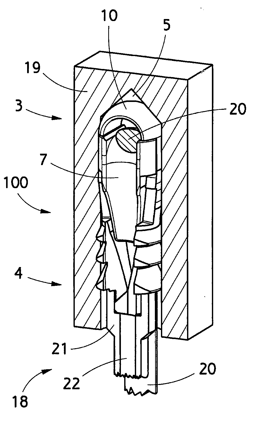
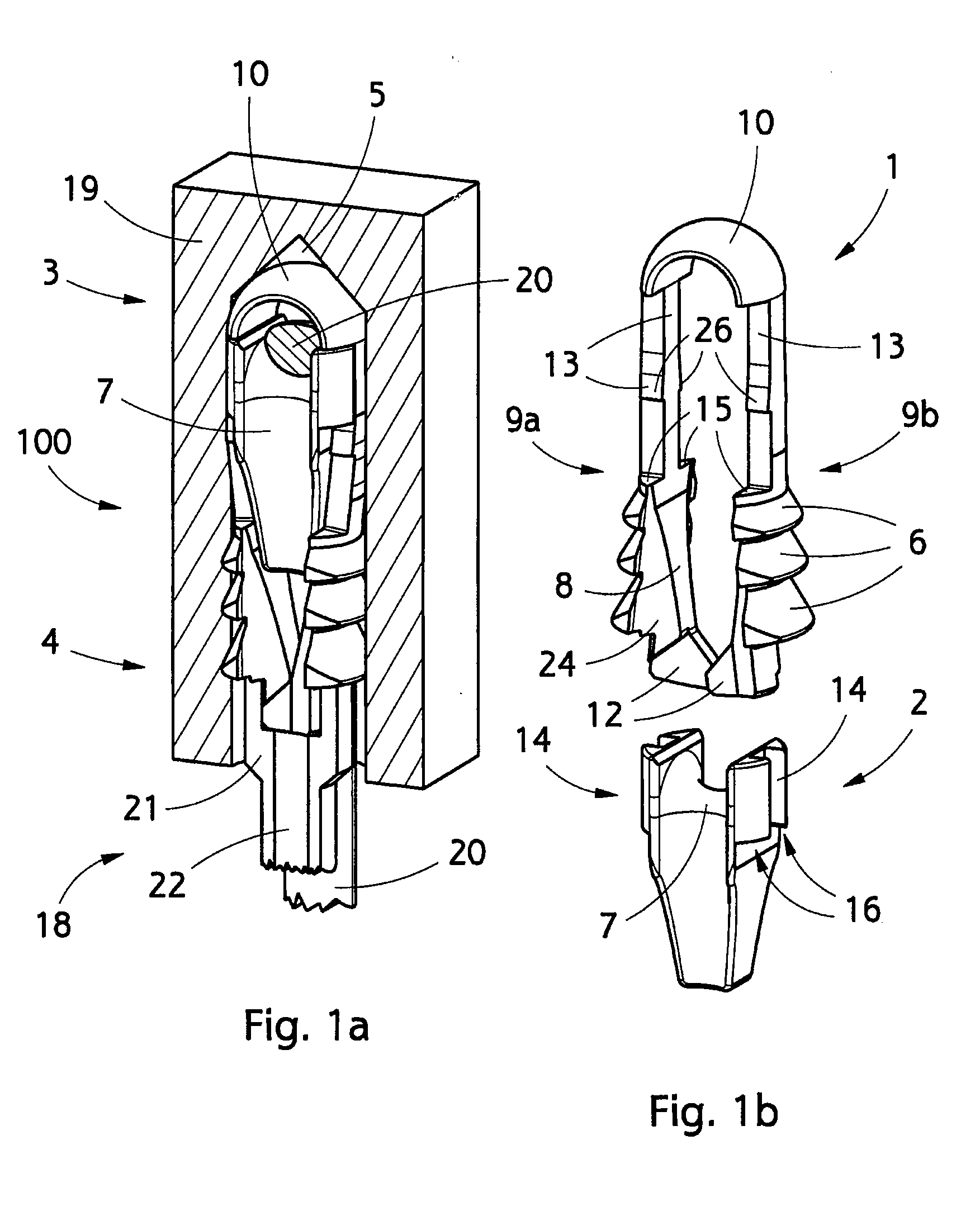
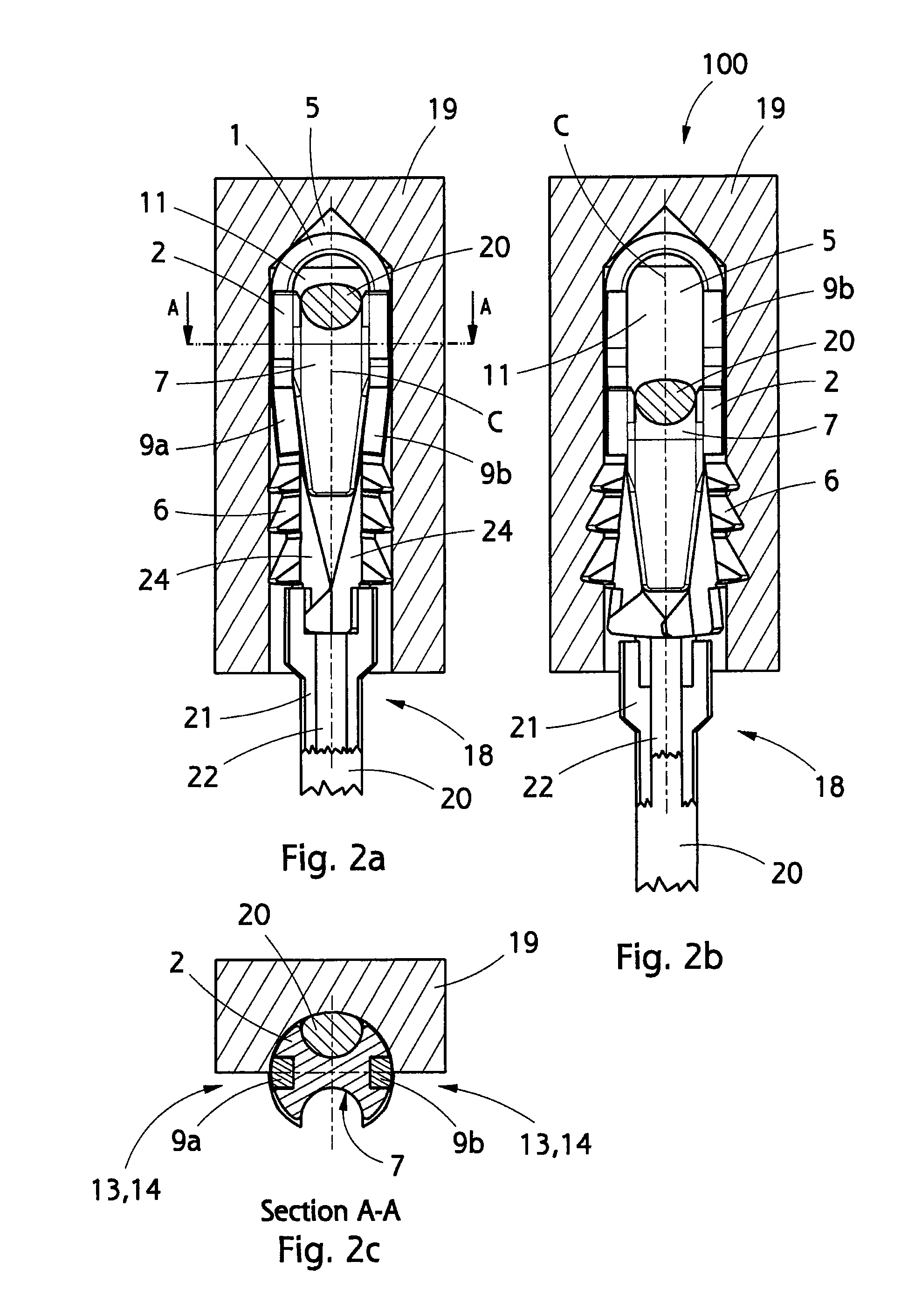
[0030]FIG. 1a is a schematic perspective view of an implant according to the invention fitted in a drill hole in the bone, and FIG. 1b is a perspective view of the implant parts of FIG. 1a, with the parts detached from one another.

[0031]The implant 100 is inserted in a hole 5 in the bone 19, the hole being in this case a bottom hole made by drilling. Making a hole 5 in the bone is known per se, and hence it is not discussed in this specification in any greater detail. It should be noted, however, that the hole 5 may also be a through-hole. In ACL or PCL operations the bone 19 is either the femur or the tibia.

[0032]The figures only show a part of the bone 19 that is cut into a cylindrical shape with a rectangular bottom.

[0033]The implant 100 comprises a first part 1 and a second part 2, which are advantageously made of biodegradable material, whereby the system will break down the implant 100 with time.

[0034]The parts 1 and 2 may be manufactured of polymer, copolymer, polymer compoun...


PUM


Abstract

The invention relates to an implant for securing a flexible piece to bone. The implant comprises a first part and a second part, a distal end that is to be inserted first in a hole in the bone, and a proximal end that is at the opposite end of the implant in relation to the distal end. The first part comprises securing means for securing the implant to said hole. The second part comprises a groove that receives the flexible piece to be secured by means of the implant. The second part is arranged to be mobile in relation to the first part in the direction of the longitudinal centre line of the implant. The contact surfaces between the first and the second parts comprise wedging surfaces such that as the second part is shifted towards the proximal end of the implant, said securing means move away from said centre line.

Description

RELATED APPLICATION[0001]This application is a continuation of European application no. 06111376.7, filed Mar. 20, 2006, which is hereby incorporated herein by reference in its entirety for all purposes.BACKGROUND OF THE INVENTION[0002]The invention relates to an implant for securing a flexible piece to bone, the implant comprising a first part and a second part, a distal end intended for being inserted first in a hole in the bone and a proximal end at the opposite end of the implant in relation to the distal end.[0003]The invention also relates to the use of the implant for securing a flexible piece to the bone.[0004]The invention further relates to the use of the implant in ACL or PCL operations.[0005]The invention still further relates to the use of the implant in a double-bundle reconstruction.[0006]There are known a large number of different implants intended for use in securing various grafts to bone. Perhaps the best-known operation in this line is replacement of a damaged an...

Claims


Application Information

Patent Timeline
20 Sep 2007
Publication
US20070218424A1
IPC
A61C8/00
CPC
A61F2/0805; A61F2/0811; A61F2002/0882; A61F2002/0852; A61F2002/0835
Inventors
VUORISALO, VESA; KOLJONEN, JUKKA