Thermoelectric conversion module and method of manufacturing the same

a technology of thermal conversion module and thermal conversion module, which is applied in the direction of thermoelectric devices with peltier/seeback effect, basic electric elements, electric apparatus, etc., can solve the problems of difficult efficient energy recovery, inability to increase t in equation (1), and restricted use of these metals in a high temperature/highly oxidizing atmospher

Inactive Publication Date: 2007-09-27
KK TOSHIBA
View PDF3 Cites 48 Cited by
  • Summary
  • Abstract
  • Description
  • Claims
  • Application Information

AI Technical Summary

Benefits of technology

[0059]Additional advantages and modifications will readily occur to those skilled in the art. Therefore, the invention in its broader aspects is not limited to the specific details and representative embodiments shown and described herein. Accordingly, various modifications may be made without departing from the spirit or scope of the general inventive concept as defined by the appended claims and their equivalents.

Problems solved by technology

Since efficient use of energy is a crucial problem in the near future when exhaustion of natural resources is a worry, various systems have been devised.
However, while these materials have high thermoelectric conversion efficiency, it is difficult to efficiently recover the energy since thermoelectric performance is low at a temperature exceeding 250° C. More specifically, ΔT in equation (1) cannot be increased when thermoelectric performance at a high temperature is low.
There are two problems of development for enhancing the operating temperature of the thermoelectric conversion member: one is an essential one whether the thermoelectric transducer is able to exhibit a desired performance, and the other is an adjunctive one in practical use.
However, use of these metals in a high temperature / highly oxidizing atmosphere is restricted since they have a quite high affinity with oxygen and are less resistant to oxidation.
For this reason, heat also flows through the glass film other than the thermoelectric transducers to cause heat energy loss.
As a consequence, complicated and precise work is inevitable for assembling the members into a module.
In particular, the step of alternately arranging the p-type and n-type semiconductor thermoelectric transducers is quite difficult as the density of arrangement of the semiconductor thermoelectric transducers is higher.

Method used


Image

  • Thermoelectric conversion module and method of manufacturing the same
  • Thermoelectric conversion module and method of manufacturing the same
  • Thermoelectric conversion module and method of manufacturing the same

Examples


example 1

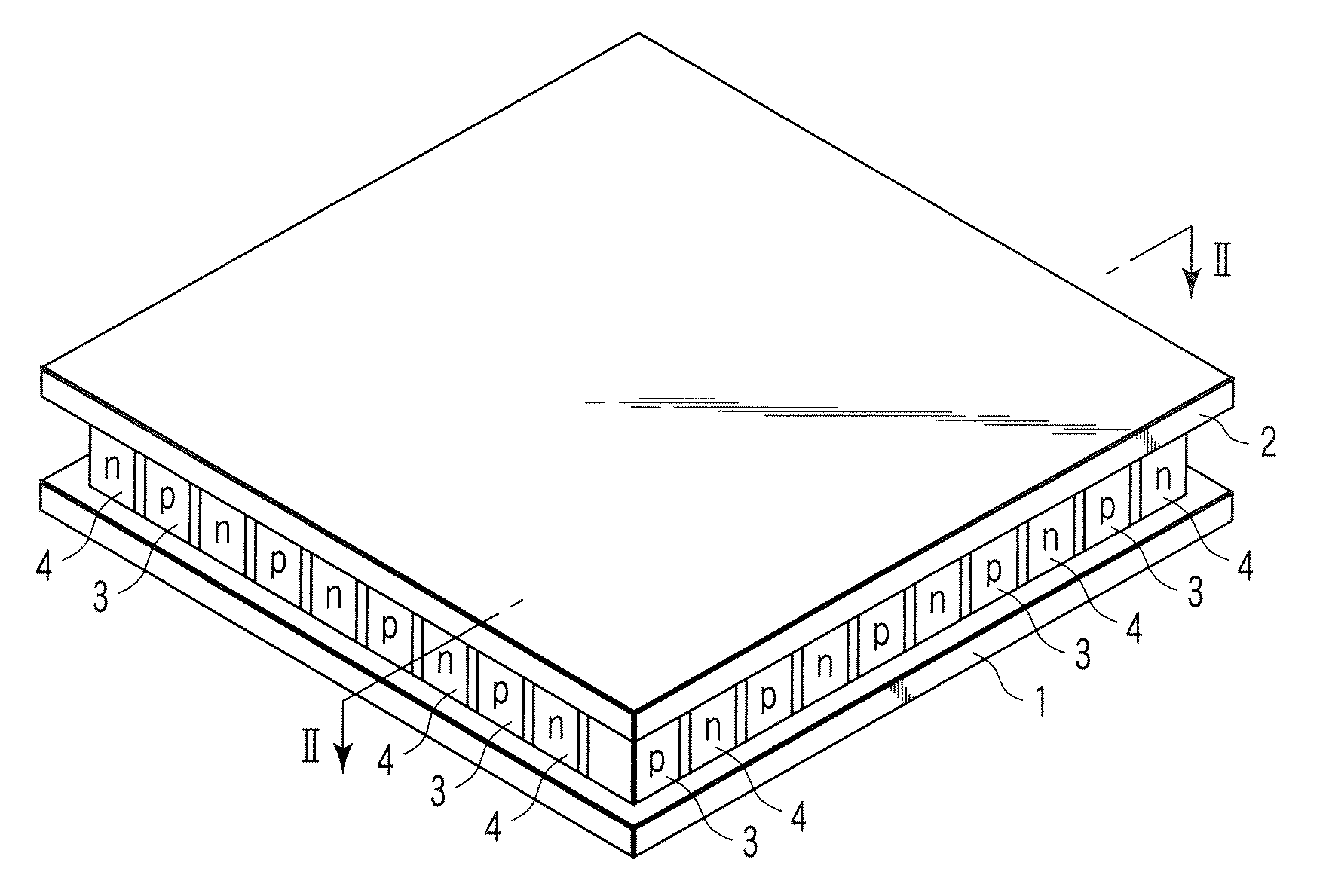
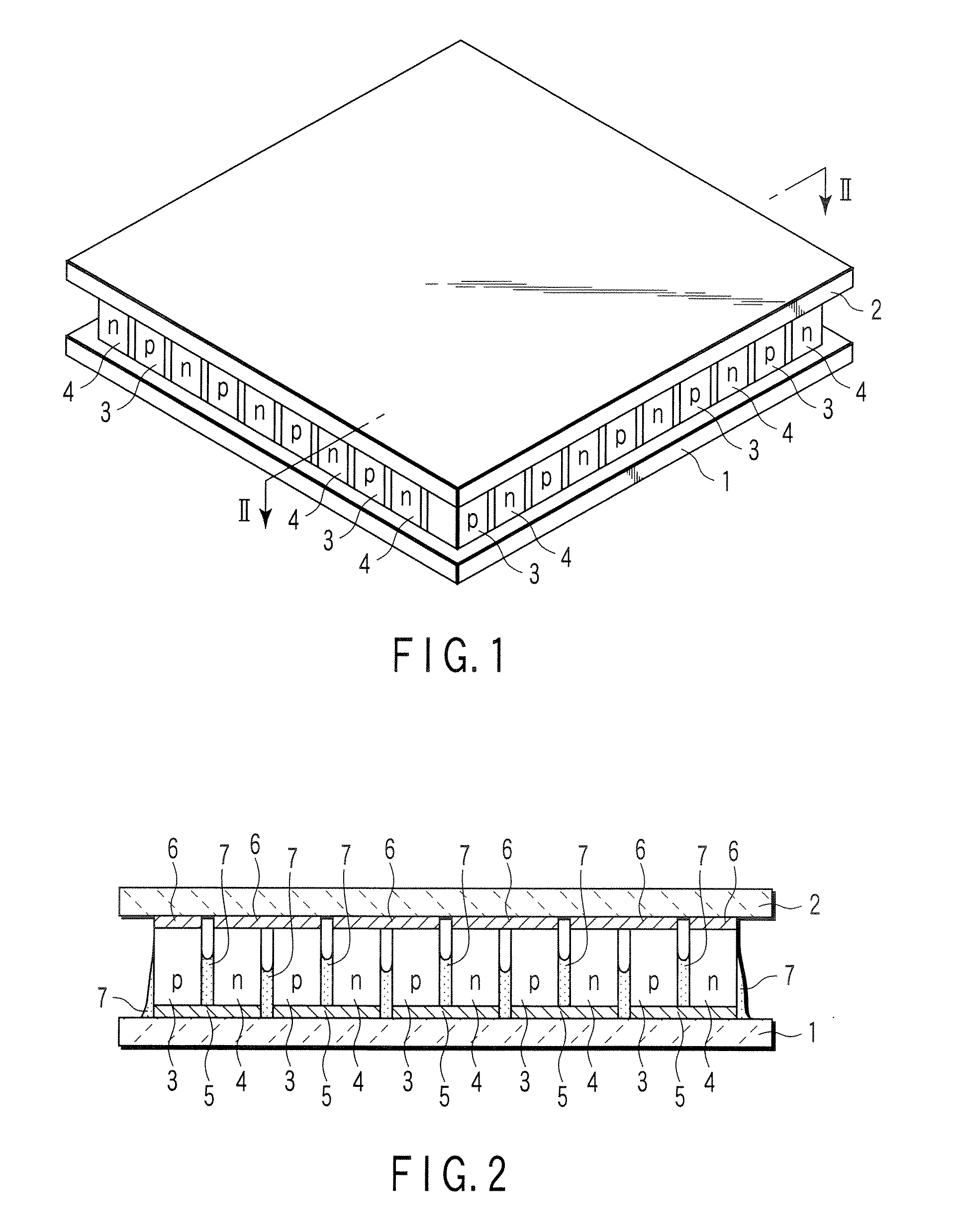
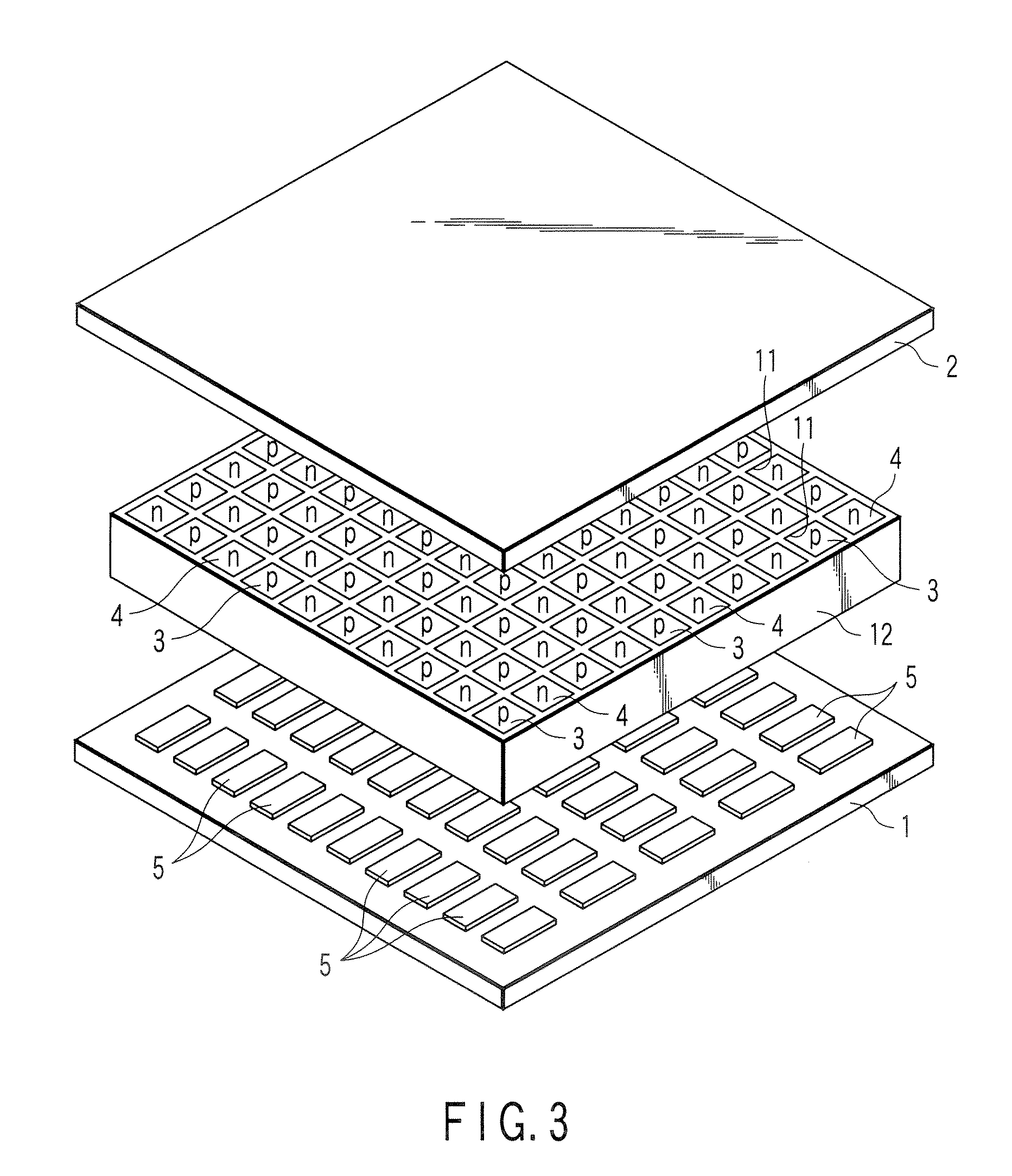
[0053]A paste was prepared by mixing a lead-free glass powder (trade name: JV-35, manufactured by Matstunami Glass Industry Ltd.) in a solution comprising 5% by weight of polyvinyl alcohol (PVA) dissolved in dimethylsulfoxide (DMSO). Then, the paste was extruded with a die and dried to obtain a honeycomb frame having 10×10 square through holes. Subsequently, 50 square columns each of p-type and n-type half-Heusler thermoelectric transducers (100 columns in total) were inserted into the through holes of the honeycomb frame such that p-type and n-type thermoelectric transducers were arranged as a checker to one another. (Ti0.3Zr0.35Hf0.35)—CoSb0.85Sn0.15 was used as the p-type thermoelectric conversion material, and (Ti0.3Zr0.35Hf0.35)—NiSn0.994Sb0.006 was used as the n-type thermoelectric conversion material.

[0054]Then, the honeycomb frame having the thermoelectric transducers inserted therein was sandwiched between first and second insulated substrates made of silicon nitride cerami...


PUM


Abstract

There is provided a thermoelectric conversion module comprising a first insulated substrate, a plurality of columnar p-type and n-type semiconductor thermoelectric transducers alternately arranged on the first insulated substrate, a second insulated substrate arranged so as to face the first insulation with interposition of the semiconductor thermoelectric transducers, first electrodes arranged between the first insulated substrate and the respective semiconductor thermoelectric transducers, and second electrodes arranged between the second insulated substrate and the respective semiconductor thermoelectric transducers, the first and second electrodes electrically connecting the p-type and n-type semiconductor thermoelectric transducers in series, and a glass film coated on the exposed surface of each first electrode at the first insulated substrate side and on a part of the exposed surfaces of the p-type and n-type semiconductor thermoelectric transducers directed from the first electrode to the second electrode.

Description

CROSS-REFERENCE TO RELATED APPLICATIONS[0001]This application is based upon and claims the benefit of priority from prior Japanese Patent Application No. 2006-083366, filed Mar. 24, 2006, the entire contents of which are incorporated herein by reference.BACKGROUND OF THE INVENTION[0002]1. Field of the Invention[0003]The invention relates to a thermoelectric conversion module and a method of manufacturing the same.[0004]2. Description of the Related Art[0005]Since efficient use of energy is a crucial problem in the near future when exhaustion of natural resources is a worry, various systems have been devised. Among these systems, thermoelectric transducers that generate thermal electromotive force by taking advantage of the so-called Seebeck effect are expected as means for recovering energy that has been wastefully discharged in the environment in the system that affords a temperature difference. The thermoelectric transducers are used as a module in which p-type semiconductor therm...

Claims


Application Information

Patent Timeline
Patent Type & Authority Applications(United States)
IPC IPC(8): H01L35/28
CPCH01L35/32H10N10/17
Inventor SHUTOH, NAOKITAKEDA, HIROMITSUSAKURADA, SHINYA
Owner KK TOSHIBA
Why Eureka
Try Eureka