Method to reduce image sticking in plasma display panels

a plasma display panel and image sticking technology, applied in the direction of instruments, static indicating devices, etc., can solve the problems of limited pixel shift, image sticking still occurs in the plasma display panel, and the original font of the plasma display panel cannot be completely dark, so as to reduce the amount of image sticking, reduce the brightness, and minimize the effect of image sticking

Inactive Publication Date: 2007-09-27
MARKETECH INT
View PDF3 Cites 12 Cited by
  • Summary
  • Abstract
  • Description
  • Claims
  • Application Information

AI Technical Summary

Benefits of technology

[0020] A method to reduce image sticking of a plasma display panel can actively detect static pixel in the images in the PDP and can reduce the brightness (discharge frequency) in the static region for a minimized amount of image sticking. For a large-area or local static image, the same level of image sticking can be realized without any influence upon normal display of images, nor removing image sticking by means of all-white display heating. This will facilitate efforts to improve considerably the performance and quality of the PDP.

Problems solved by technology

However, the Plasma Display Panel (PDP) still faces the problem of image sticking, wherein image retention takes place after a static image is displayed on a PDP for a certain period of time.
However, this method has poor performance, owing to the fact that only a few pixels shift by this method.
As shown in FIG. 1, since the font size of “PDP” represents a wide area of pixels, a limited pixel shift cannot bring the original font of “PDP” into a completely dark region.
This method, however, has the following limitations:
a. Unable to identify accurately gray level reversal time.
b. Unable to generate gray level reversal images of a static display.
In such case, it is unlikely to generate gray level reversal images of “Bshi” font to reduce image sticking.
However, striped images will occur on the display, leading to discomfort of the users.
However, this method generally requires a long-lasting heating process, and also leads to unsatisfactory result in this regard.

Method used


Image

  • Method to reduce image sticking in plasma display panels
  • Method to reduce image sticking in plasma display panels
  • Method to reduce image sticking in plasma display panels

Examples


Embodiment Construction

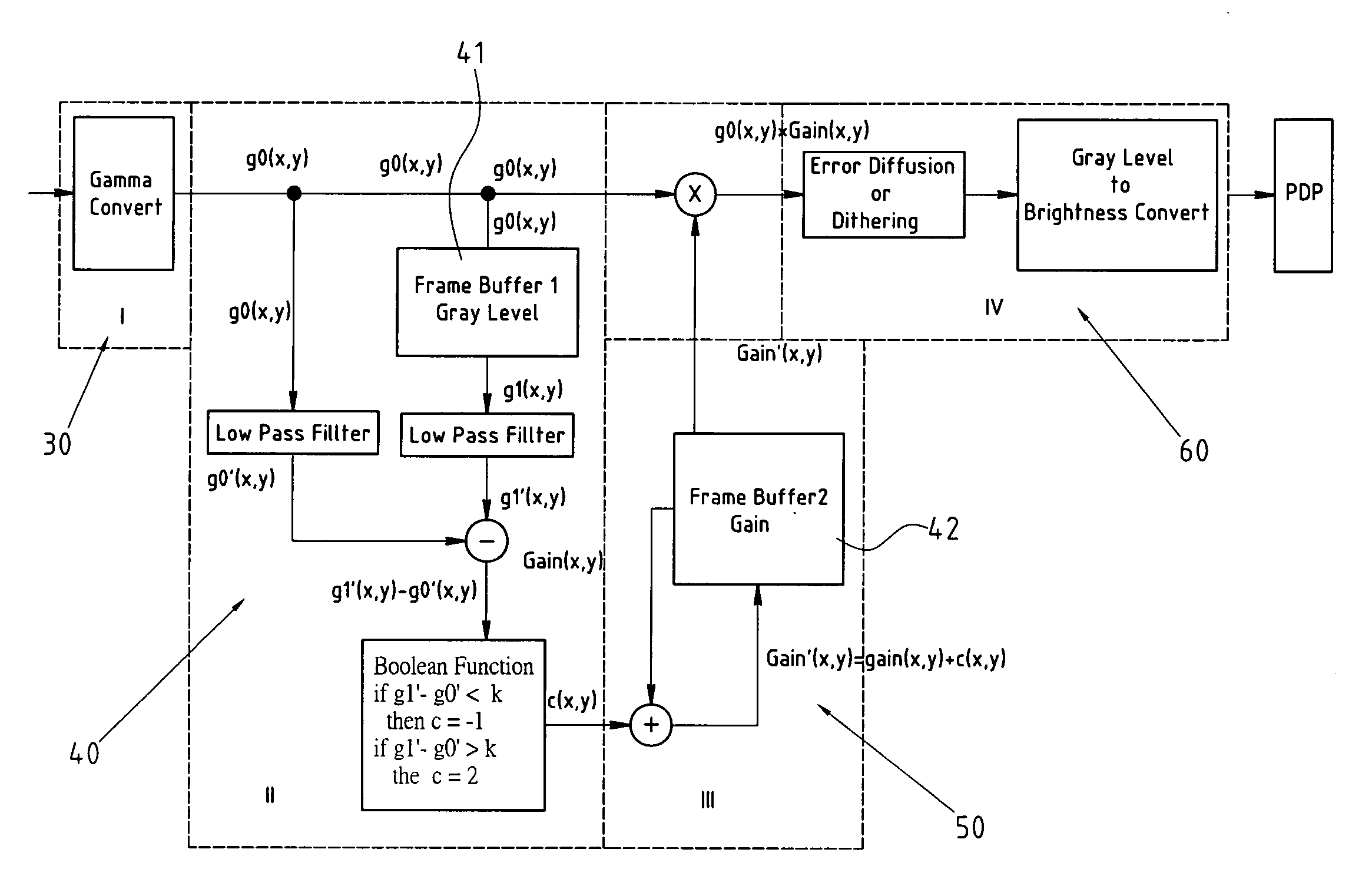
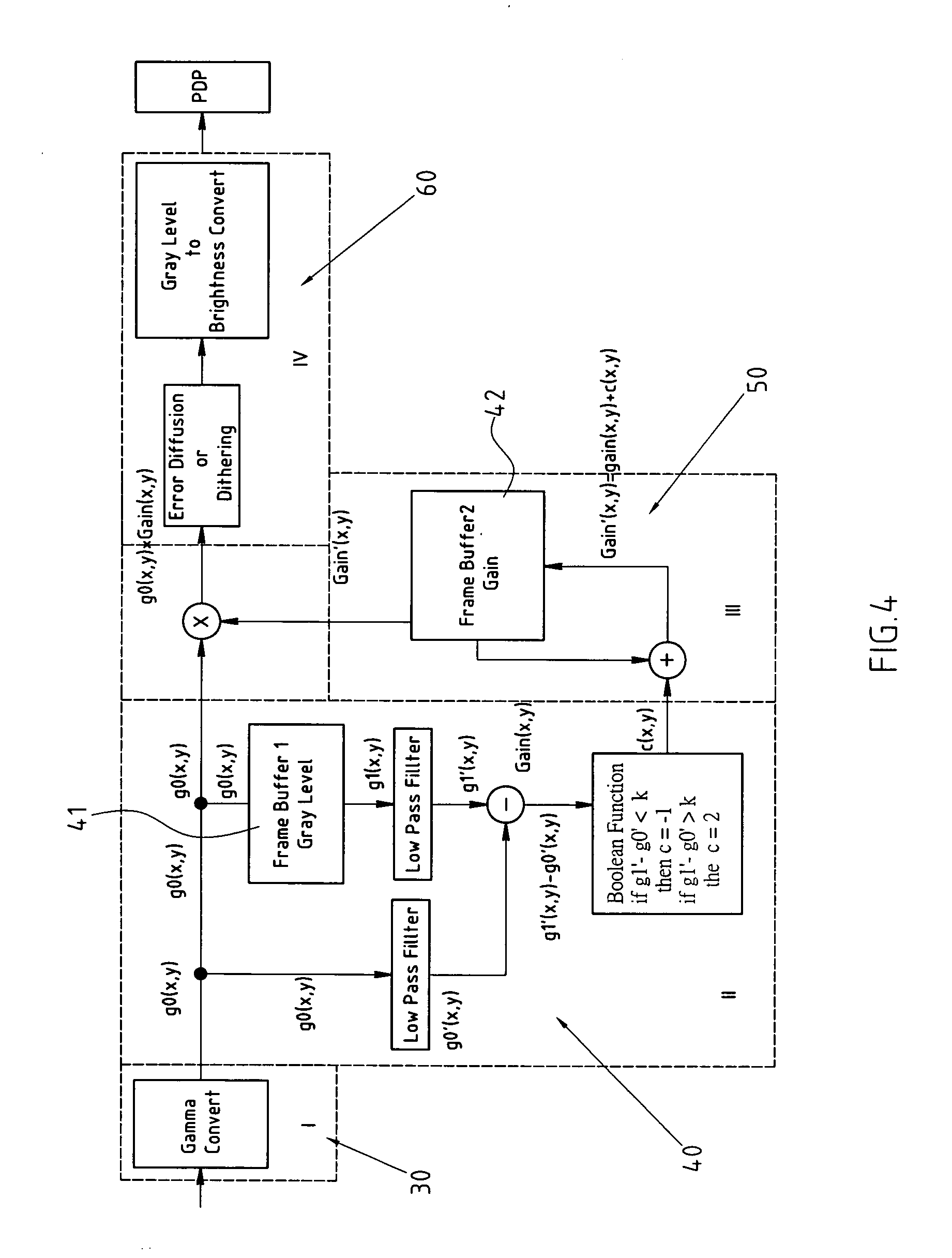
[0026]FIG. 4 depicts an improved embodiment of a Plasma Display Panel (PDP) for decreased image sticking, which places no restriction on the claims. A method to reduce image sticking of plasma display panel, comprises four parts: a Gamma converter 30, static image detector 40, brightness regulator 50, and gray level promoter and brightness converter 60.

[0027] The Gamma converter 30 is aimed to convert the relationship between gray level and brightness of an input signal into a linear relation. For example, Gamma 0.45 shows the relationship between the gray level and brightness of a traditional video signal. Gamma converter 30 permits a Gamma 2.2 conversion of the input signal, thus achieving linear relationship between gray level and brightness. This makes it possible to accurately predict the expected brightness based on a gray level via a simple circuit.

[0028] The Static image detector 40 includes a frame buffer 41 is used to record the image at time t, and after a period of tim...


PUM


Abstract

The method to reduce image sticking in a plasma display panel (PDP) includes four steps. There is converting a relationship between gray level and brightness of an input signal into a linear relation by a converter. Next, there is recording an image with a static image detector at time t using a frame buffer, and after a period of time Δt, comparing the image at time t with the image at time t+Δt, thereby identifying static or dynamic images in the pixel. Then, there is recording a gain of every pixel by a brightness regulator using an image gains memory buffer zone, the gain being regulated according to detection results of the static image detector. Finally, there is improving gray level performance of output images by a gray level promoter and brightness converter. Thus, method actively detects static pixels and reduces brightness in the static region for minimized image sticking.

Description

RELATED U.S. APPLICATIONS [0001] Not applicable. STATEMENT REGARDING FEDERALLY SPONSORED RESEARCH OR DEVELOPMENT [0002] Not applicable. REFERENCE TO MICROFICHE APPENDIX [0003] Not applicable. FIELD OF THE INVENTION [0004] The present invention relates generally to a method to reduce image sticking in plasma display panels. More particularly, the invention allows active detection of static pixels in images and reduction of brightness for minimized image sticking. BACKGROUND OF THE INVENTION [0005] The Plasma Display Panel (PDP) is a currently mainstream, large-sized, and thin-profile display panel featuring a bigger frame, higher quality, a wider visual angle and lower radiation. However, the Plasma Display Panel (PDP) still faces the problem of image sticking, wherein image retention takes place after a static image is displayed on a PDP for a certain period of time. As illustrated in FIG. 1, when a Plasma Display Panel 10 highlights the font of “PDP”20A, and then becomes a dark dis...

Claims


Application Information

Patent Timeline
Patent Type & Authority Applications(United States)
IPC IPC(8): G09G3/28
CPCG09G3/2944G09G2320/0271G09G2320/046G09G2360/16G09G2320/0673G09G2320/103G09G2320/0626
Inventor KAO, HSU-PINSHAN, YI-CHIATSAI, TSAN-HUNGKAO, HSU-CHIA
Owner MARKETECH INT
Why Eureka
Try Eureka