Driving circuit with protection module for back light module

Inactive Publication Date: 2007-09-27
BEYOND INNOVATION TECH
View PDF12 Cites 25 Cited by
  • Summary
  • Abstract
  • Description
  • Claims
  • Application Information

AI Technical Summary

Benefits of technology

[0019]Since the present invention uses the transformer to transform the voltage source into the driving voltage to drive the light source, the present invention could adj

Problems solved by technology

The boost magnification (Vout/VDD) provided by the boost circuit in FIG. 1 is not high enough to provide such a high driving voltage.
Therefore, the design of using the inductor 109 as a boost element is certainly limited by value of the voltage source VDD, such that the requirement for

Method used


Image

  • Driving circuit with protection module for back light module
  • Driving circuit with protection module for back light module
  • Driving circuit with protection module for back light module

Examples


Embodiment Construction

[0028]The preferred embodiments of the present invention will be illustrated in detail below with reference to appended drawings, wherein the appended drawings show various preferred embodiments of the present invention. The present invention can also be accomplished by many different ways, and is not limited to the embodiments described herein. The object of providing embodiments herein is to make those skilled in the related art fully comprehend the scope of the present invention. In the following part, similar reference numbers represent similar elements.

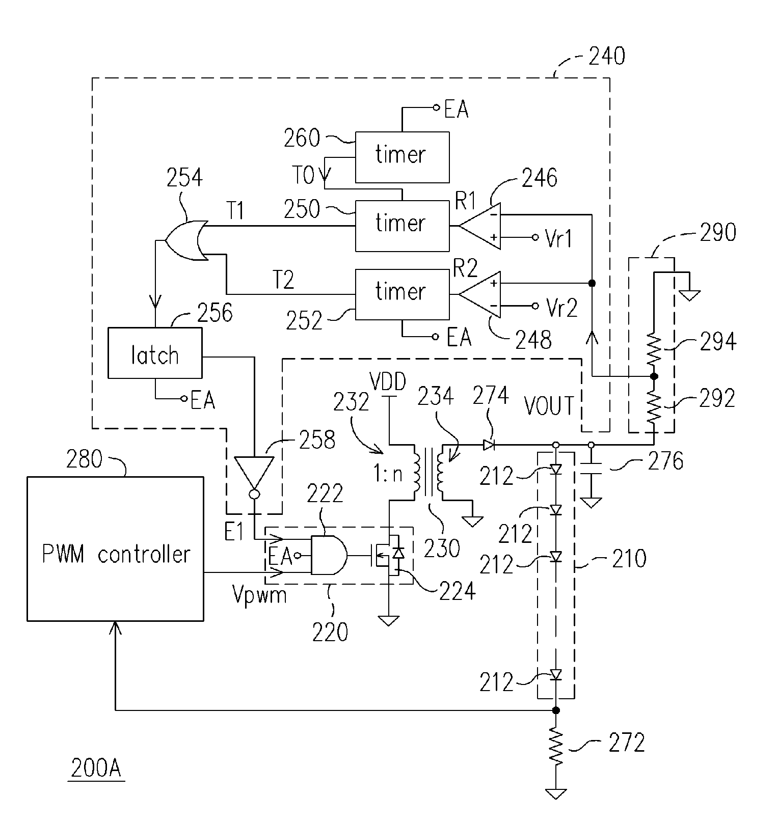
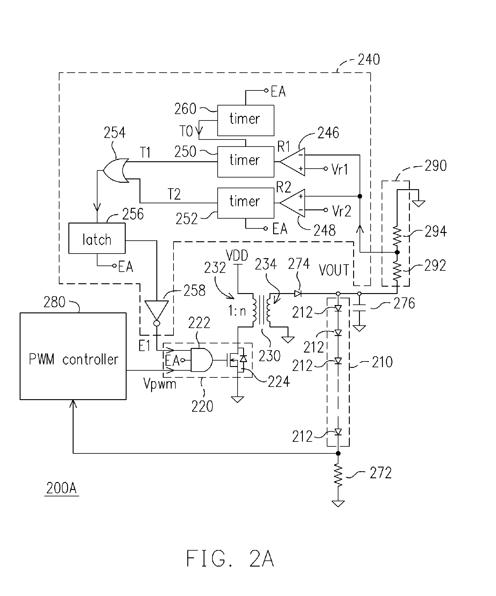
[0029]FIG. 2A is a circuit diagram of a back light module according to a first embodiment of the present invention. Referring to FIG. 2A, a back light module 200A provided by the present invention comprises a light source module 210 and a driving circuit constituted by a driving module 220, a transformer 230, and a protection module 240. In the embodiment of the present invention, the light source module 210 may be formed by a pl...


PUM


Abstract

A driving circuit for a plurality of light-emitting diodes (LEDs) comprises a transformer, a driving module, and a protection module. The transformer has a primary coil and a secondary coil, wherein a first end of the primary coil is coupled to a voltage source. Furthermore, a second end of the primary coil of the transformer is coupled to the driving module. The driving module determines whether to deliver electrical power to the transformer according to a pulse-width modulation (PWM) signal and an error signal. The protection module is coupled to the secondary coil. When a driving voltage output by the transformer to the LEDs is less than a first preset voltage or greater than a second preset voltage, the protection module generates the error signal to the driving module.

Description

CROSS-REFERENCE TO RELATED APPLICATION[0001]This application claims the priority benefit of Taiwan application serial no. 95109796, filed on Mar. 22, 2006. All disclosure of the Taiwan application is incorporated herein by reference.BACKGROUND OF THE INVENTION[0002]1. Field of Invention[0003]The present invention relates to a driving technology for a plurality of light-emitting diodes (LEDs). More particularly, the present invention relates to a driving technology for LEDs used in a back light module.[0004]2. Description of Related Art[0005]In a conventional back light module, a cold cathode fluorescent tube is commonly used as a light source. However, in recent years, with the advance of the photoelectric element technique, a light-emitting diode has many advantages, such as small size, low operating voltage, long lifespan and high color saturation. Therefore, using LEDs as the light source of the back light module has become another new choice.[0006]Due to a factor of manufacturin...

Claims


Application Information

Patent Timeline
IPC IPC(8): G09G3/36H01L33/00H05B37/02
CPCG09G3/3406G09G2320/064G09G2330/04Y02B20/346H05B33/0851H05B33/0887Y02B20/341H05B33/0818H05B45/50H05B45/10Y02B20/30H05B45/382H05B45/385H05B45/38
Inventor YU, CHUNG-CHELEE, LI-MINKAO, CHIN-FA
Owner BEYOND INNOVATION TECH
Why Eureka
Try Eureka