Optical element, display device, and terminal device

a technology of optical elements and terminal devices, applied in non-linear optics, instruments, optics, etc., can solve the problems of reducing the efficiency of the manufacturing process, unable to recognize the displayed content, and unable to see from the side or read the information displayed by a third party, etc., to achieve excellent display quality, reduce the effect of moiré stripes formed by light passing through the optical elemen

Inactive Publication Date: 2007-09-27
NEC LCD TECH CORP
View PDF5 Cites 38 Cited by
  • Summary
  • Abstract
  • Description
  • Claims
  • Application Information

AI Technical Summary

Benefits of technology

[0049]According to the present invention, moiré stripes formed by light passing through the optical element can be reduced, and high transmittance or high luminance can be maintained in an optical element formed by stacking together a light-direction regulating element in which transparent regions and non-transparent regions are periodically arranged in alternating fashion in a plane in one or two dimensions, and a two-dimensional lattice shee...

Problems solved by technology

For example, it is thereby impossible or extremely difficult for a third party present beside the user to see from the side or read the information displayed when the anti-eavesdropping device is mounted on the liquid crystal display of the information display.
However, since the light control film must be cut at an angle, the efficiency of the manufacturing process declines when the angle β is too large.
As a result, light is not transmitted to positions where the display unit is viewed at an angle to the left or right in the horizontal direction, the screen is darkened when viewed from such a position, and it becomes impossible to recognize the displayed content.
However, the conventional techniques described above have such problems as those described below.
Specifically, in the conventional display device provided with a privacy enabling device described in Japanese Patent Application Laid-Open No. 2003-131202, significant moiré is created by the pixels of the display device and the colored silicone rubber sheets constituting the privacy enabling device that is the light-direction regulating element, and display quality is significantly reduced.
A conventional technique for creating a high-directivity display involves providing the display panel with a louver in which transparent parts and light-blocking parts are in a one-dimensi...

Method used


Image

  • Optical element, display device, and terminal device
  • Optical element, display device, and terminal device
  • Optical element, display device, and terminal device

Examples


first embodiment

[0084]The optical element, display device, and terminal device according to embodiments of the present invention will be described in detail with reference to the accompanying drawings. The optical element according to the present invention will first be described in detail based on the operating principle thereof.

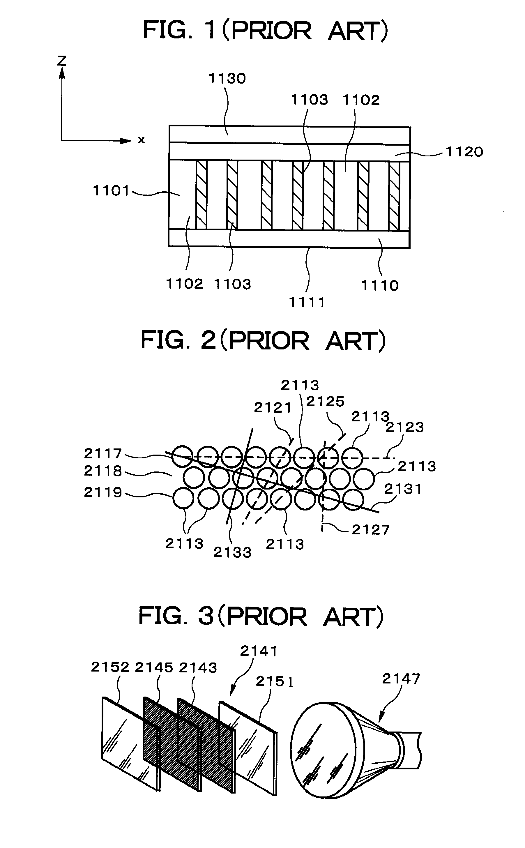
[0085]The optical element according to the first embodiment of the present invention is formed by stacking together a light-direction regulating element in which transparent regions and non-transparent regions are periodically arranged in alternating fashion in a plane in one dimension, and a two-dimensional lattice sheet in which transparent regions and non-transparent regions are periodically arranged in alternating fashion in two dimensions. The light-direction regulating element has one-dimensional translational symmetry due to the one-dimensional periodic structure thereof, and the two-dimensional lattice sheet has two-dimensional translational symmetry due to the two...

third embodiment

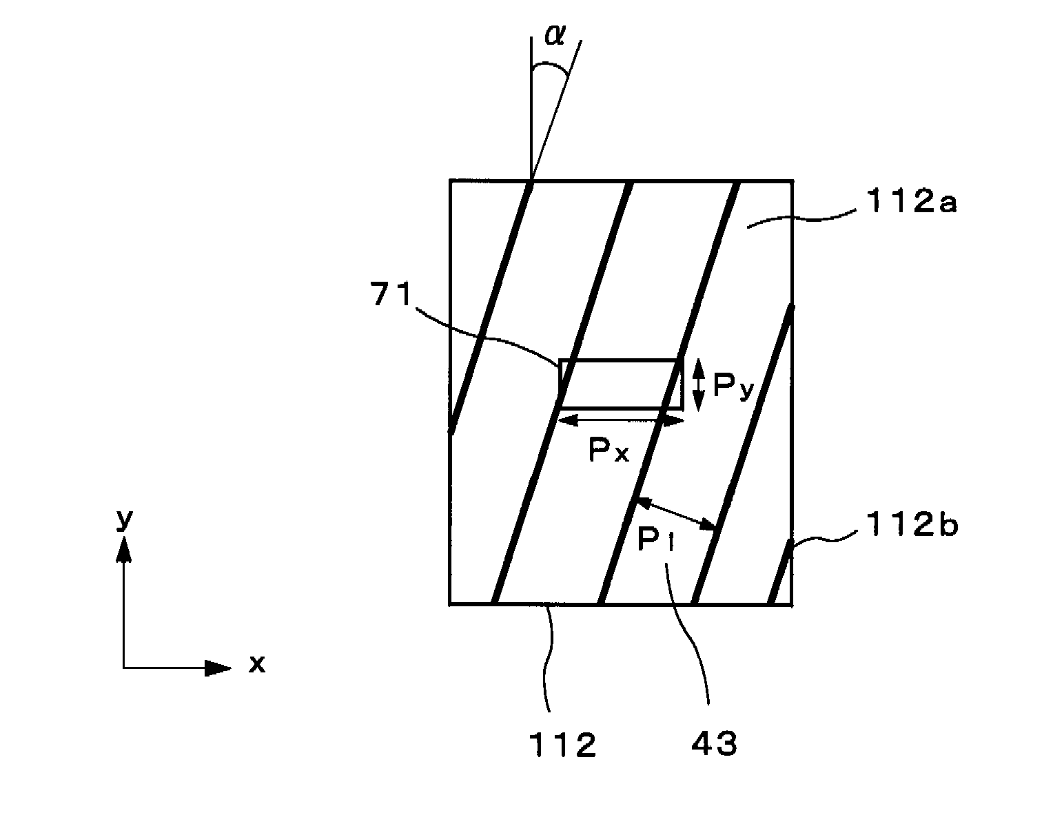
[0123]The display device according to the present invention will next be described. FIG. 21 is a perspective view showing the display device according to the present embodiment; FIG. 22 is a top view showing the louver used in the present embodiment; and FIG. 23 is a top view showing the positional relationship between the louver and a pixel in the present embodiment.

[0124]As shown in FIG. 21, a self-luminous display panel 6 is provided, and a louver 112 that is a light-direction regulating element is provided on the self-luminous display panel 6 in the display device 2 of the present embodiment. The louver 112 is a sheet in which a transparent material and a non-transparent material are periodically arranged in one dimension, and the thickness of the louver is measured in the direction perpendicular to the display plane. An organic EL (Electroluminescence) panel, for example, may be applied as the self-luminous panel 6. The display panel 6 has a plurality of pixels periodically arr...

fourth embodiment

[0140]the present invention shall be described next. FIG. 24 is a perspective view showing a display device according to the present embodiment; and FIG. 22 is a top view showing a louver used in the present embodiment.

[0141]A light source device 1 is provided in a display device 2 according to the present embodiment, and a transmissive liquid crystal panel 7 is provided above the light source device 1, as shown in FIG. 24. The light source device 1 is composed of a light guide plate 3; a light source 51 provided to a side surface of the light guide plate 3; and a louver 112, which is a light-direction regulating element, disposed on a front surface side of the light guide plate 3, i.e., on the side of an observer in a +z direction. The light source 51 is, e.g., an LED (light emitting diode).

[0142]In the present embodiment, a xyz orthogonal coordinate system such as described below is used for the sake of simplicity. A direction extending from the light source 51 toward the light gu...


PUM


Abstract

A plurality of pixels is arranged periodically in the x-axis direction and the y-axis direction in the display panel of a display device, and because light is blocked by the portion other than the open part in each pixel, the display panel has a two-dimensional lattice structure. The pixels are rectangular, and the length Px of the long edges in the x direction is larger than the length Py of the short edges in the y direction. A louver, in which transparent regions and non-transparent regions are arranged periodically in a one-dimensional direction, is provided on the display panel, and the angle formed by the x axis and the one-dimensional period direction of the louver is 45 degrees or less, and preferably 10 degrees or less. This configuration makes it possible to obtain an optical element having high directivity, reduced moiré, and high transmittance. It is also possible to obtain a display device having excellent display quality into which the optical element is incorporated.

Description

BACKGROUND OF THE INVENTION[0001]1. Field of the Invention[0002]The present invention relates to a display device that produces excellent display quality with reduced moiré.[0003]2. Description of the Related Art[0004]Due to recent advances in technology, display panels have been deployed in a range of devices that includes monitors, television sets, and other large terminal devices; notebook PCs (Personal Computer), cash dispensers, vending machines, and other mid-sized terminal devices; and personal TVs (Television), PDAs (Personal Digital Assistant: personal information terminal), mobile telephones, mobile gaming devices, and other small terminal devices that are used in a variety of locations. Because of their thin profile, light weight, small size, low energy consumption, and other advantages, display devices that use liquid crystals are particularly common in terminal devices.[0005]Among these terminal devices, small-to-medium-sized terminal devices are characteristically used...

Claims


Application Information

Patent Timeline
IPC IPC(8): G02F1/1335
CPCG02F1/133509G02F2201/124G02F1/134363
Inventor NIIOKA, SHINYAUEHARA, SHIN-ICHISUMIYOSHI, KENKANEKO, SETSUO
Owner NEC LCD TECH CORP
Why Eureka
Try Eureka