
External cavity laser

a laser and external cavity technology, applied in the field of external cavity lasers, can solve the problems of laser system instability, laser output hopping and other times of laser system hopping

Pending Publication Date: 2007-09-27
AKONIA HOLOGRAPHICS
View PDF38 Cites 24 Cited by
  • Summary
  • Abstract
  • Description
  • Claims
  • Application Information

AI Technical Summary

Problems solved by technology

Tuning such a laser by merely adjusting the grating angle may result in the laser occasionally “hopping” from one cavity mode to another cavity mode.
Mode hops may result in the instability of the laser output by the laser system.

Method used


Image

  • External cavity laser
  • External cavity laser
  • External cavity laser

Examples


Embodiment Construction

[0030]It is advantageous to define several terms before describing the invention. It should be appreciated that the following definitions are used throughout this application.

Definitions

[0031]Where the definition of terms departs from the commonly used meaning of the term, applicant intends to utilize the definitions provided below, unless specifically indicated.

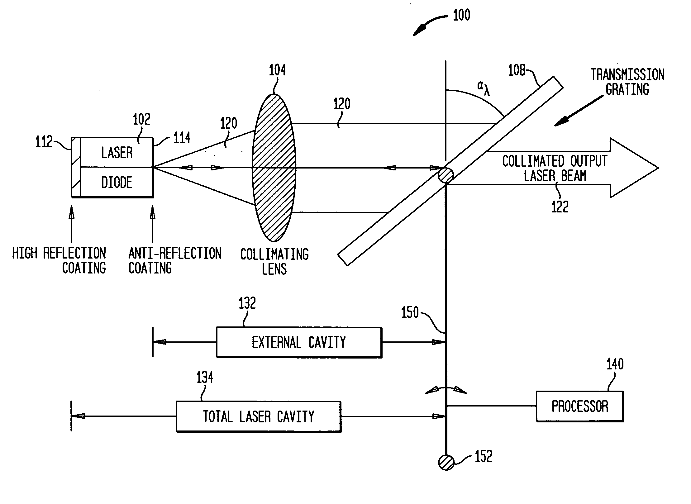
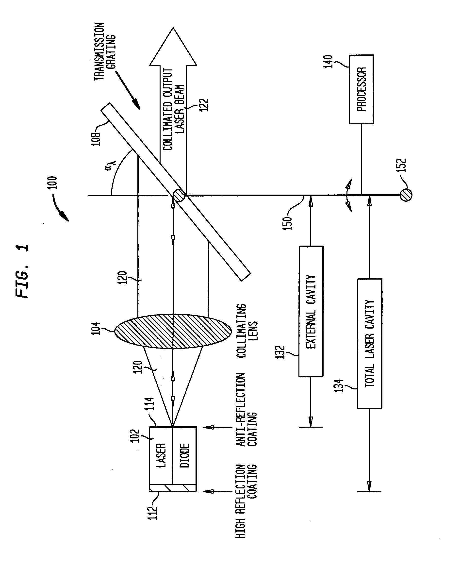
[0032]For the purposes of the present invention, the term “light source” refers to a source of electromagnetic radiation having a single wavelength or multiple wavelengths. The light source may be from a laser, a laser diode, one or more light emitting diodes (LEDs), etc.

[0033]For the purposes of the present invention, the term “coherent light beam” refers to a beam of light including waves with a particular (e.g., constant) phase relationship, such as, for example, a laser beam.

[0034]For the purposes of the present invention, the term “processor” refers to a device capable of executing instructions and / or implementing logic...


PUM


Abstract

Embodiments of systems and methods are provided for a tunable laser device. The tunable laser device may include a diffraction grating connected to a pivot arm that pivots the diffraction grating about a pivot point to tune the laser device. In pivoting the diffraction grating about the pivot point, both the wavelength to which the diffraction grating is tuned and the length of the optical cavity may be changed. The length of the pivot arm may be selected to reduce the number of mode hops of the tunable laser device when tuning the laser device over its tuning range.

Description

CROSS-REFERENCE TO RELATED APPLICATIONS[0001]This application makes reference to and claims the priority date of co-pending U.S. Patent Application 60 / 780,354, entitled “External Cavity Laser”, filed Mar. 9, 2006. The entire disclosure and contents of the above application is hereby incorporated by reference.BACKGROUND[0002]1. Field of the Invention[0003]The present invention relates generally lasers, and more particularly, to external cavity lasers.[0004]2. Related Art[0005]The use of an external laser cavity with a spectrally selective element has been used for several decades to create a laser with a narrower spectral linewidth than is available with the non-wavelength selective mirrors in the laser cavity of the typical laser. In addition, the tenability of the spectrally selective element may create a laser with an agile wavelength that may be both narrow in line width and cover a broad tuning range. The spectrally selective element in many non-integrated external cavity lasers...

Claims


Application Information

Patent Timeline
Patent Type & Authority Applications(United States)
IPC IPC(8): H01S3/10H01S5/00H01S3/08
CPCH01S5/141H01S3/0014H01S3/0621H01S3/08009H01S3/08086H01S3/086H01S3/1055H01S3/139
Inventor HUNTER, SUSANKRNETA, VLADIMIRENSHER, JASON
Owner AKONIA HOLOGRAPHICS
Learn More