Audio Communication Method And Device

a communication method and audio technology, applied in the field of audio communication methods and devices, can solve the problems of insufficient jitter, longer delay in audio communication, and shorter delay, and achieve the effect of suppressing audio quality degradation and increasing delay

Inactive Publication Date: 2007-09-27
NEC CORP
View PDF11 Cites 41 Cited by
  • Summary
  • Abstract
  • Description
  • Claims
  • Application Information

AI Technical Summary

Benefits of technology

[0012] Accordingly, the present invention has as an object to provide an audio communication method and a device that enables switching to a different encoding format even during audio communication and that can suppress audio quality degradation and an increase in delay.

Problems solved by technology

When the buffer is large in size, a larger jitter can be treated, however, the delay in audio communication becomes longer because time is required until audio is reproduced.
On the other hand, when a buffer is made small in size, delay becomes shorter, however, jitter cannot be absorbed sufficiently, and therefore, there is a problem in that the reproduced audio is disconnected.
In the above-mentioned audio communication using the VoIP technique, though the encoding bit rate, which is the speed of the encoding process, can be changed, the encoding format used per one session is fixed, and therefore, an optimal encoding format is not always selected according to the needs of the user and the state of the network.
However, it is difficult to adopt such a method, except for a transmission path with a sufficient usable transmission band.
Also, when the buffer control method described in the above patent documents is applied to audio communication, in Japanese Patent Laid-Open No. 2002-204258, there is a possibility that the audio will be paused by spillover data from the buffer when the amount of received data is larger than the amount of data to be reproduced.
Further, in Japanese Patent Laid-Open No. 2003-087318, there is a problem that a delay is increased because a sufficient buffer size must be ensured in order to adjust the cycle of the encoding process.
Furthermore, in Japanese Patent Laid-Open No. 2003-249977, jitter or a dropout is generated in the notified message in itself, when an unstable transmission path, like a best-effort network and a wireless network, is used.
Also, when the fluctuations in jitter are large, it is difficult to notify and control a message in response to these.
Further, in audio communication using the VoIP technique, when there is a characteristic difference between audio communication devices that perform audio communication, a difference is generated in the audio capture or the reproduction cycle and causes the reproduced audio to be disconnected.
Also, since a delay caused by the encoding process is generated in addition to the transmission delay caused by the network, in some encoding formats, there are situations in which the number of samples required for encoding is increased and the time required to ensure sample points does not satisfy the delay request for the audio communication.
Further, when the up-link and the down-link in audio communications are different in a communication environment, such as a usable band and a delay, in order to match the communication environments among the audio communication devices that perform communication, the audio encoded data has to be transmitted and received at a low bit rate so as to meet the low processing capacity, and therefore, there is a problem that the quality of the reproduced audio will be degraded.
Further, when encoding formats are arbitrarily switched in order to respond flexibly to delay and to user requests about audio quality, with only switching, the audio data becomes discontinuous during the switching, and therefore, there is also a problem that audio degradation, such as a pause in the produced audio, occurs.

Method used


Image

  • Audio Communication Method And Device
  • Audio Communication Method And Device
  • Audio Communication Method And Device

Examples


first embodiment

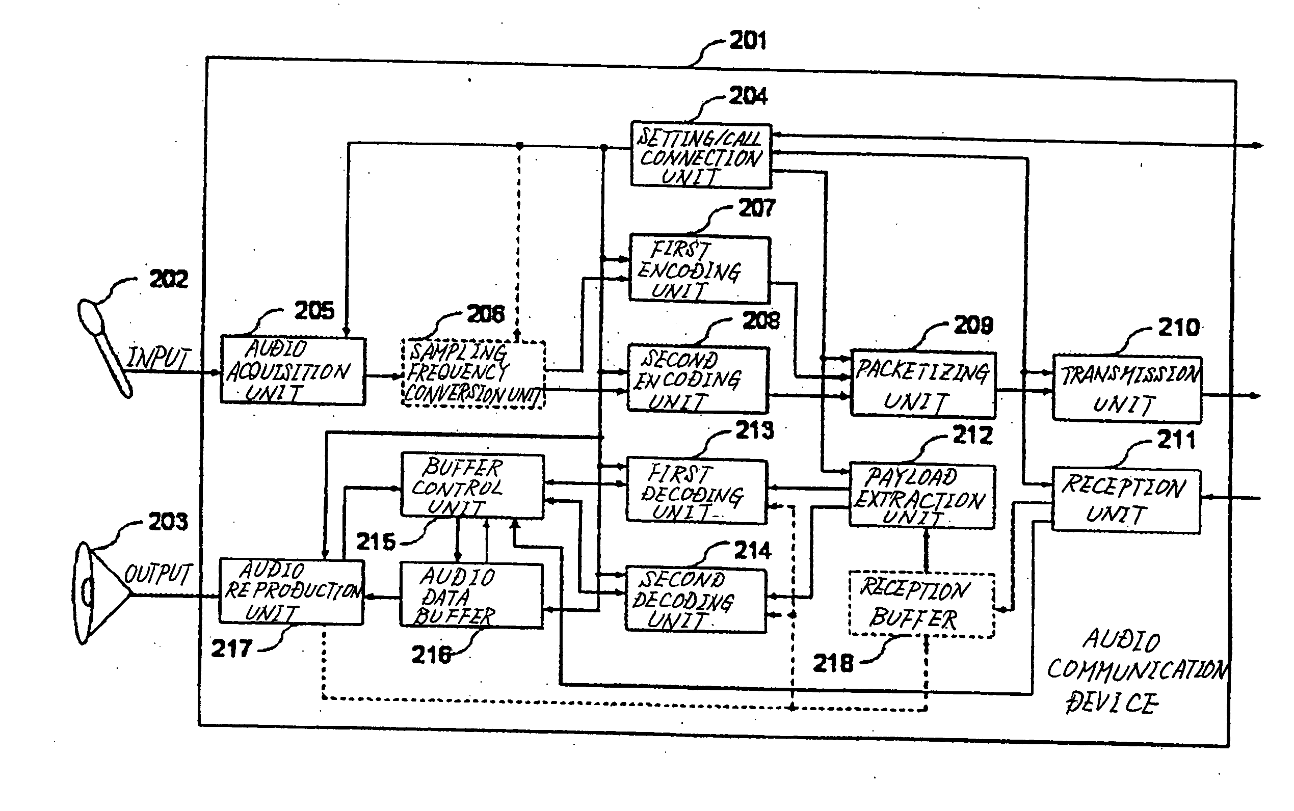
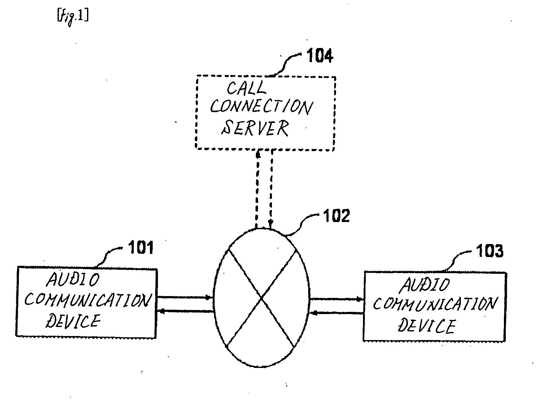
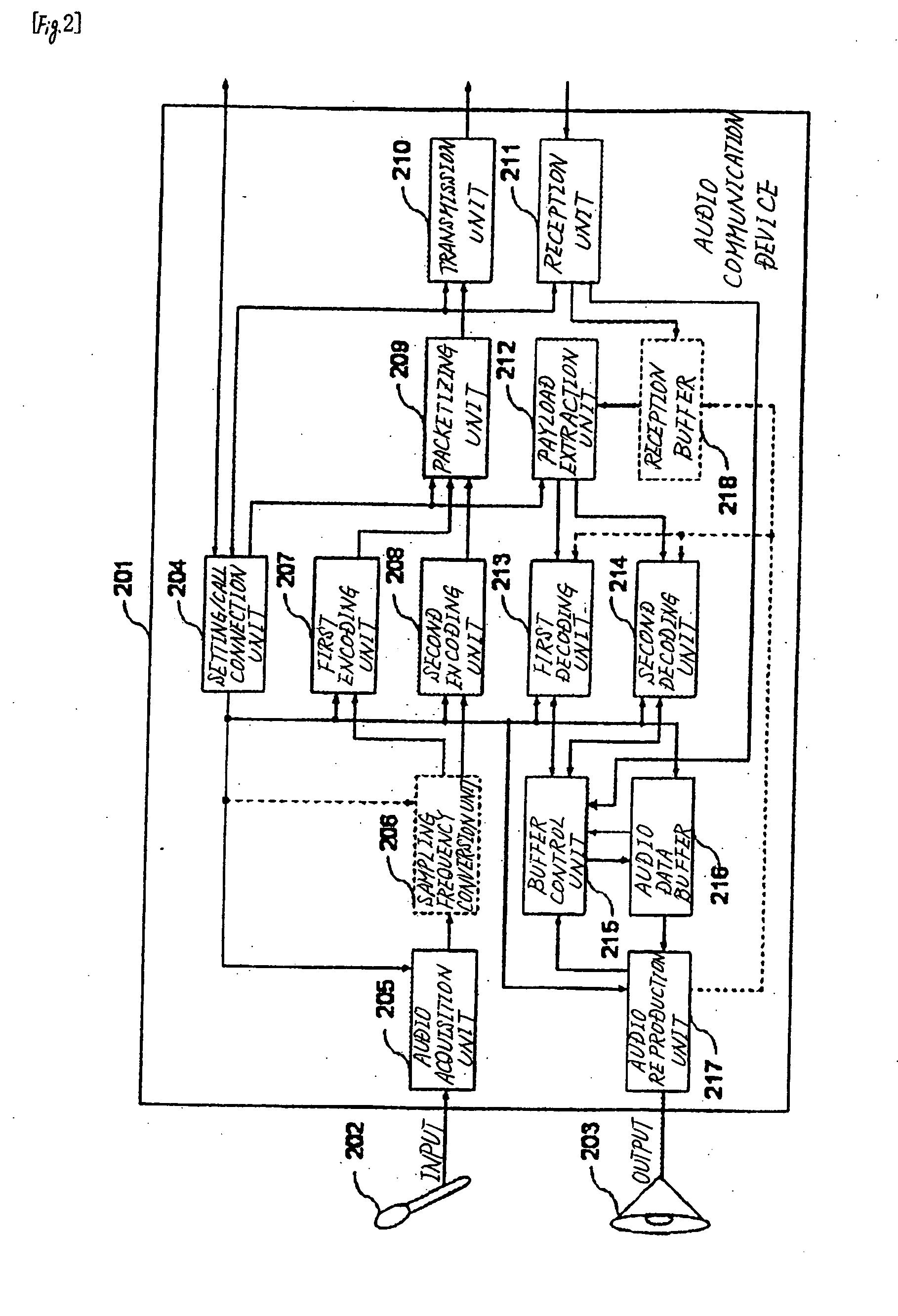
[0022]FIG. 1 is a block diagram showing a configuration example of an audio communication system, and FIG. 2 is a block diagram showing a configuration example of the audio communication device according to the present invention. Also, FIG. 3 is a timing chart showing timing of the encoding process by the first encoding unit and the second encoding unit shown in FIG. 2, and FIG. 4 is a block diagram showing a configuration of the buffer control unit according to the first embodiment arranged in the audio communication device of the present invention. Incidentally, audio communication device 201 shown in FIG. 2 is a common configuration example that is available to audio communication device 101 and audio communication device 103.

[0023] As shown in FIG. 1, the audio communication system is configured by connecting audio communication device 101 and 103 that mutually transmit and receive audio data through network 102, which is an IP (Internet Protocol) network. Audio communication d...

second embodiment

[0085] Next, explanations are given of the audio communication device of the second embodiment according to the present invention with reference to drawings.

[0086]FIG. 5 is a block diagram showing a configuration of a buffer control unit according to the second embodiment in the audio communication device of the present invention.

[0087] The audio communication device of the second embodiment is different from the first embodiment in the configuration of buffer control unit 215. The other configurations and operations are similar to those of the first embodiment, and therefore detailed explanations thereof are omitted.

[0088] As shown in FIG. 5, the buffer control unit of the second embodiment has data selection determination unit 501 instead of parameter determination unit 402 and sampling frequency conversion unit 403 shown in the first embodiment. Buffer amount monitor unit 401 and padding data insertion unit 404 are similar to those of the first embodiment, and therefore explan...


PUM


Abstract

An audio communication device includes a plurality of encoding units and decoding units, and switches the encoding format from one to another according to the useable transmission band or to a user audio quality request or to a delay request. The audio encoded data that is received is decoded by selecting an optimal decoding unit according to the encoding format identifier added to the data or according to set information notified from audio communication device 201 of the communication partner. The audio data decoded is temporality stored in audio data buffer 216 and reproduced. The amount of audio data stored in the audio data buffer is controlled so that audio is reproduced without pause.

Description

TECHNICAL FIELD [0001] The present invention relates to an audio communication method and device for transmitting and receiving audio via a network. BACKGROUND ART [0002] In recent years, the audio communication in which audio data is received and transmitted by packets through a network, i.e., the so-called VoIP (Voice over IP), has been widely used. Such audio communication encodes audio (including music, various sound effects, and the like) with a predetermined encoding format and the encoded audio data is transmitted and received, thereby enabling communication with little audio quality degradation, without occupying a wide transmission band. [0003] As representative examples of the audio encoding format, G.711, G.729, AMR-NB (Adaptive Multi Rate-Narrow Band), AMR-WB (Adaptive Multi Rate-Wide Band), MPEG (Moving Picture Experts Group)-4 ACC (Advanced Audio Codec), and the like are known. The technique for distributing audio data encoded according to these encoding formats (herei...

Claims


Application Information

Patent Timeline
Patent Type & Authority Applications(United States)
IPC IPC(8): H04M11/00G10L19/00G10L19/22H03M7/30H04L12/56
CPCG10L19/24H04L47/283
Inventor DEI, HIROAKIOZAWA, KAZUNORINAKAZAWA, TATSUYAKOYAMA, KAZUHIRO
Owner NEC CORP
Why Eureka
Try Eureka