
Chaotic signal transmitter

Inactive Publication Date: 2007-09-27
SAMSUNG ELECTRO MECHANICS CO LTD
View PDF5 Cites 12 Cited by
  • Summary
  • Abstract
  • Description
  • Claims
  • Application Information

AI Technical Summary

Benefits of technology

[0018]The present invention has been made to solve the foregoing problems of the prior art and therefore an aspect of the present invention is to provide a chaotic signal transmitter which enables precise measurement of a distance between the transmitter and a receiver and.
[0019]Another aspect of the invention is to provide a chaotic signal transmitter which precisely measures a distance between the transmitter and a receiver to efficiently regulate transmission power.

Problems solved by technology

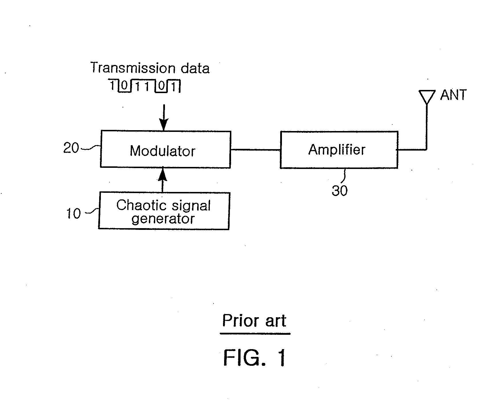
But such a typical modulation method requires complex technical interpretation for the original signal during demodulation.
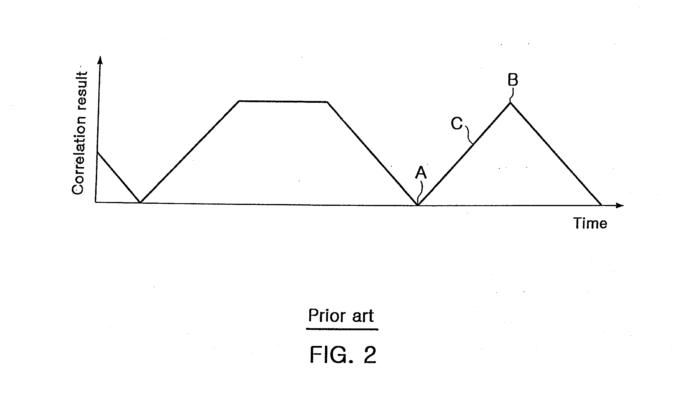
However, as shown in the graph of FIG. 2, in the conventional ultra-wide band transmitter, almost no change is exhibited in the slope C from the lowest point A to the highest point B, which makes it difficult to determine the highest point B. This in turn makes it difficult for the receiver to accurately sense the time taken from the lowest point A to the highest point B, hindering precise distance measurement.
Therefore, since the distance between the transmitter and the receiver is not measured precisely, excessive transmission power is used to transmit the signal, degrading transmission power efficiency.

Method used


Image

  • Chaotic signal transmitter
  • Chaotic signal transmitter
  • Chaotic signal transmitter

Examples


Embodiment Construction

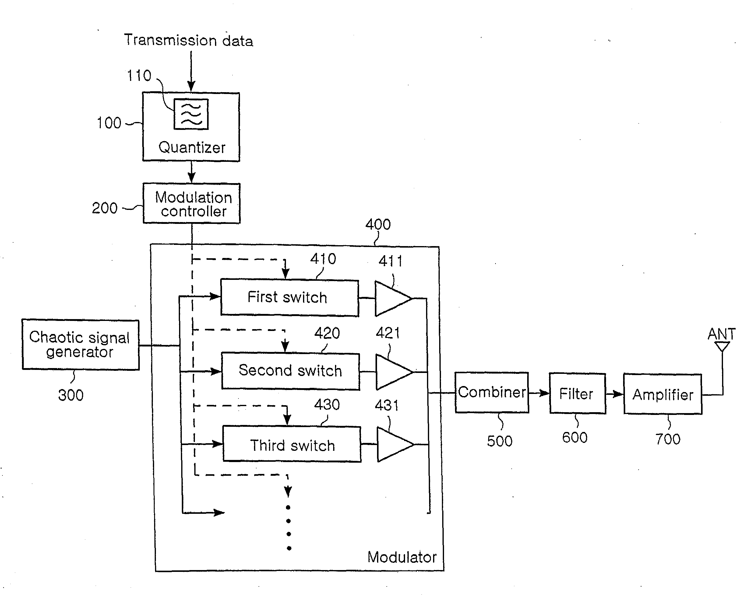
[0032]Exemplary embodiments of the present invention will now be described in detail with reference to the accompanying drawings.

[0033]FIG. 3 is a block diagram illustrating a chaotic signal transmitter according to the present invention.

[0034]Referring to FIG. 3, the chaotic signal transmitter according to the present invention includes a quantizer 100 for quantizing a transmission signal; a modulation controller 200 for controlling modulation according to the quantized transmission signal from the quantizer 100; a chaotic signal generator 300 for generating a chaotic signal; a modulator 400 for modulating the chaotic signal in a multiple On-Off Keying (OOK) mode according to the control by the modulation controller 200; and a combiner 500 for combining the plurality of modulated chaotic signals from the modulator 400.

[0035]The quantizer 100 receives a transmission signal a user desires to transmit. Preferably, the transmission signal may be a square wave pulse. The transmission si...


PUM


Abstract

The invention relates to a chaotic transmitter which can precisely measure a distance between the transmitter and a receiver, thereby efficiently regulating transmission power according to the distance. The chaotic signal transmitter includes a chaotic signal generator for generating a chaotic signal and a quantizer for quantizing a transmission signal with a predetermined number of steps. The chaotic signal transmitter also includes a modulation controller for controlling the modulation of the chaotic signal according to the quantized transmission signal. The chaotic signal transmitter further includes a modulator for modulating the chaotic signal from the chaotic signal generator in a multiple OOK mode to output a plurality of chaotic signals and a combiner for combining the plurality of modulated chaotic signals.

Description

CLAIM OF PRIORITY[0001]This application claims the benefit of Korean Patent Application No. 2006-0027153 filed on Mar. 24, 2006, in the Korean Intellectual Property Office, the disclosure of which is incorporated herein by reference.BACKGROUND OF THE INVENTION[0002]1. Field of the Invention[0003]The present invention relates to a chaotic signal transmitter and, more particularly, to a chaotic signal transmitter which can precisely measure a distance between the transmitter and a receiver using multiple On-Off Keying (OOK) modulation, thereby efficiently regulating transmission power according to the distance between the transmitter and the receiver.[0004]2. Description of the Related Art[0005]In general, a chaotic signal is characterized as an aperiodic signal with no particular phase, and a wide band signal. A typical periodic signal has a regular phase in accordance with time and thus may be distorted or cancelled when an interference signal of an antiphase is added. However, a ch...

Claims


Application Information

Patent Timeline
IPC IPC(8): H04L9/00
CPCH04L27/001Y02B60/50H04W52/283Y02E60/14F24F5/0042F24F5/0017
Inventor LEE, KWANG DUPARK, HYUNG CHULYANG, CHANG SOO
Owner SAMSUNG ELECTRO MECHANICS CO LTD
Learn More