
Digital Loudspeaker

Inactive Publication Date: 2007-09-27
1 LIMITED ST JOHN S INNOVATION CENT
View PDF93 Cites 7 Cited by
  • Summary
  • Abstract
  • Description
  • Claims
  • Application Information

AI Technical Summary

Benefits of technology

[0006] In the present invention, a practical effect is achieved somewhat similar to that produced by the abovementioned DDALs, using in some cases simpler physical hardware, which is therefore capable of manufacture at lower cost and with less complexity. Furthermore, there are practical advantages in the designs and methods of the present invention, which make the integration of a practical and useful DDAL into and around a conventional video display device possible, eliminating the requirement for an additional piece of equipment, adjacent to or separate from the video display itself.
[0010] Thus it is one of the aims of the present invention to minimise or avoid production of unwanted alias beams despite the transducer array as a whole containing a very substantial hole or gap.
[0029] In another preferred aspect of the invention, a subset of the transducers forming one of the DDAL groups are arranged in multiple substantially parallel rows with substantially similar spacing within each and every row, although the row-to-row spacing may differ from this intra-row spacing, and where the substantially parallel rows are substantially parallel to at least one significant portion of an edge of the region (e.g. where the region is substantially rectangular, the transducer rows may be parallel to at least one edge of the region). In such a case, and where it is not necessary to be able to electronically steer this DDAL beam in a plane normal to the parallel rows of transducers, the complexity of the DDAL drive and control electronics may be simplified by driving adjacent transducers in adjacent parallel rows (i.e. transducers in the same ‘column’) with signals of the same identical delay (rather than different delays), whilst retaining the ability to vary the signal delay from transducer to transducer within each row. Such an arrangement provides one-dimensional (1D) beam forming and electronic steering in a plane parallel to the parallel rows of transducers. If the separation between the outer edges of transducers in the first and last rows is substantial, and specifically comparable to or greater than a wavelength of sound in air at a frequency of interest for directing the sound, then the parallel row array will be substantially directional if not electronically steerable in the plane orthogonal to the parallel rows of transducers, and in this case it may be advantageous to tilt the plane of the rows of transducers relative to the region so as to orientate the directional beam in a preferred direction relative to the region. A similar effect may be achieved by using just one (or a few) row(s) of transducers with high aspect ratio (e.g. elliptical transducers) with their short axis parallel to the row direction.
[0032] As already mentioned, one application for the invention is to provide surround sound with less cabling and no need for satellite speakers. Another application is to output two beams of audio signals, each signal representing a completely different programme, for example a television programme audio signal. If the beams are steered in different directions two users standing or sitting in different positions can receive different audio programmes. This can be combined with a split screen VDS to allow two users to watch different TV channels, with full sound, without disturbing each other.

Problems solved by technology

A problem arises when a set of transducers in a non-contiguous group is used to direct sound beams in a direction spanning the non-contiguous part (i.e. the “hole” separating distant transducers of the same group).
This problem of alias beams arises when the hole, that is, the area within the array devoid of transducers, has one or both dimensions (horizontal or vertical) greater than half a wavelength of sound at a given frequency.
Due to the problem of alias beams, it has heretofore not been thought possible to provide adequate beam steering using a DDAL that is not contiguous and area extensive.

Method used


Image

  • Digital Loudspeaker
  • Digital Loudspeaker
  • Digital Loudspeaker

Examples


Embodiment Construction

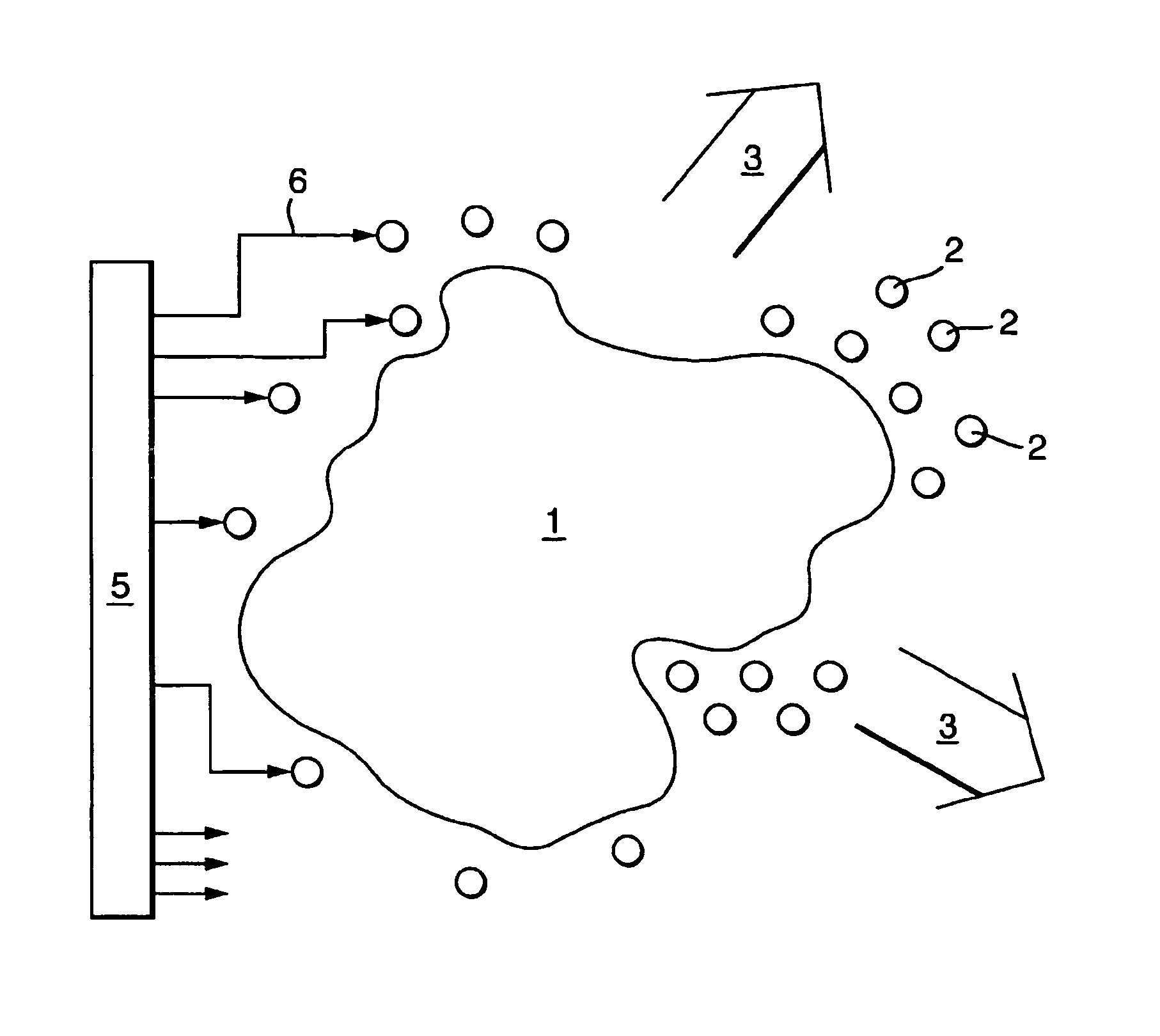
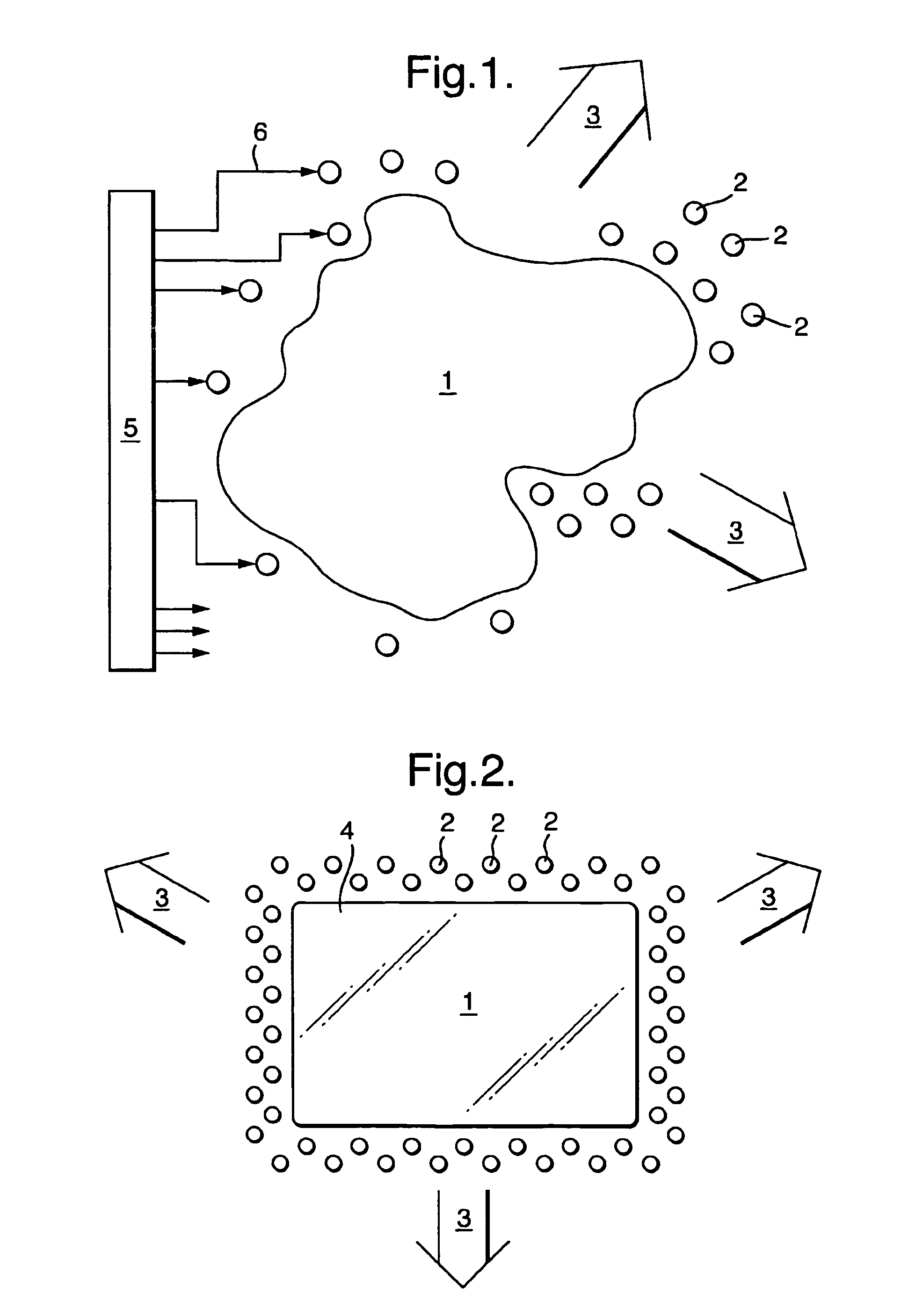
[0042]FIG. 1 is a schematic representation of an example of a Digital Loudspeaker of the invention. A closed planar region 1 has at its periphery a set of transducers, represented by the closed circles in FIG. 1, three of which are labelled 2. Each transducer 2 is very substantially smaller in area than the region 1. The set of transducers 2 forms a Digital Delay Array Loudspeaker, DDAL, which may be operated in one or more discrete transducer groups, each group preferably forming a DDAL so as to produce one or more different and simultaneous sound fields, represented schematically by the broad arrows 3. The transducers 2 are controlled by DDAL control and drive electronics, shown schematically as enclosed in the box 5. Each transducer 2 is connected to the control electronics, as indicated by arrows of the type 6 (for clarity, not all the connections 6 are shown).

[0043]FIG. 2 is a schematic representation of a further embodiment of the invention. The region 1 about which the trans...


PUM


Abstract

A loudspeaker comprises a region devoid of electroacoustic transducers and at least two groups of electroacoustic transducers at the periphery of the region. Each of the groups is configured to produce a different sound field representative of an audio signal and each of the groups comprise a different set of transducers. This allows a more compact loudspeaker to be provided because the transducers can be located around the periphery of a visual display screen. Sound quality is not compromised because groups of transducers forming a subset of the totality of transducers are used for each sound signal, thereby avoiding alias beams.

Description

FIELD OF THE INVENTION [0001] The invention relates to loudspeakers suitable for home entertainment or professional sound reproduction applications. More specifically, it relates to a device including an array of electro-acoustic transducers capable of receiving a multi-channel audio input signal and producing independently steerable and focusable beams of audible sound. BACKGROUND OF THE INVENTION [0002] Digital phased-array loudspeakers (or more correctly, Digital Delay Array Loudspeakers), hereinafter DDALs, are known in the art (for example, international Applications published as WO01 / 23104 and WO02 / 078388.) These patent applications teach how to use DDALs to produce full surround sound, in for example its common 5.1 channel form, using just one DDAL, and in this manner replacing a multitude of separate loudspeakers, dispersed around a listening room or space, and also dispensing with all the necessary connecting wires required for conventional multiple-discrete-loudspeaker sur...

Claims


Application Information

Patent Timeline
IPC IPC(8): H04R5/02H04N5/64H04R1/40H04R3/12
CPCH04N5/642H04R1/403H04R2205/022H04R5/02H04R2203/12H04R3/12H04N5/64H04R1/04
Inventor BIENEK, IRVING ALEXANDERDAVIES, JAMESEASTON, MARK GEORGEGOUDIE, ANGUS GAVINHOOLEY, ANTHONYMAKINO, SHINICHIMORLEY, ANDREWRICHARDS, DAVID CHARLES WILLIAMSHEPHERD, MARK RICHARDWINDLE, PAUL RAYMOND
Owner 1 LIMITED ST JOHN S INNOVATION CENT
Features
  • Generate Ideas
  • Intellectual Property
  • Life Sciences
  • Materials
  • Tech Scout
  • Unparalleled Data Quality
  • Higher Quality Content
  • 60% Fewer Hallucinations
Learn More