Split roller bearing device

a technology of roller bearings and bearings, which is applied in the direction of bearing units, rigid support, machines/engines, etc., can solve the problems of increasing difficult to reduce the cost and weight of the shaft support part, and the mounting operation takes a lot of man-hour and complicated, so as to achieve easy support, reduce the number of parts, and high precision

Inactive Publication Date: 2007-09-27
JTEKT CORP
View PDF0 Cites 22 Cited by
  • Summary
  • Abstract
  • Description
  • Claims
  • Application Information

AI Technical Summary

Benefits of technology

[0040] When the inner ribs are formed at the outer ring split part, the cage with the rollers held is axially restricted and the roller bearing including the cage with the rollers held can be mounted around not only the smaller diameter portion formed on the shaft body (at the smaller diameter portion, the cage with the rollers held is axially restricted by the edge walls of both axial sides of the smaller diameter portion), but also the larger diameter portion formed on the shaft body and a portion having the same diameter as the other portion of the shaft body. In particular, when the roller bearing is mounted around the larger diameter portion of the shaft body, the outer circumferential surface of the larger diameter portion functions as the inner ring, and the smaller diameter portion protrudes radially outward from the other portion of the shaft body, so that it is facilitated to grind and polish the inner ring and it is achievable to make the inner ring in high precision.
[0041] According to the above-described second aspect of the invention, it is facilitated to support rotatably a shaft body by mounting a split roller bearing around the shaft body. Further, since a cap member, such as a cam cap, is not needed, the number of parts is reduced and the weight of the shaft support part and cost are reduced accordingly.

Problems solved by technology

Therefore, the mounting operation takes lots of man-hour and complicated.
Further, according to the above configuration, since the outer ring and the cage of the roller bearing are each separated into two sections and the cam cap is needed in order to fix the outer ring, the number of parts increases and it is difficult to reduce cost and weight of the shaft support part.

Method used


Image

  • Split roller bearing device
  • Split roller bearing device
  • Split roller bearing device

Examples


first embodiment

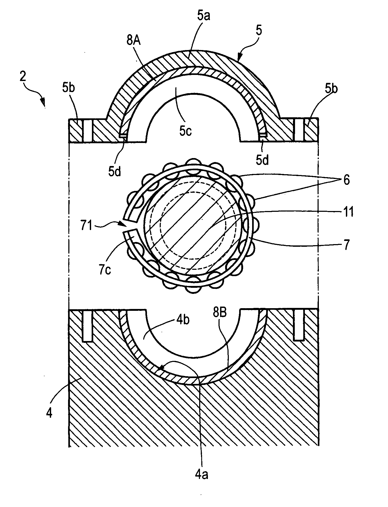
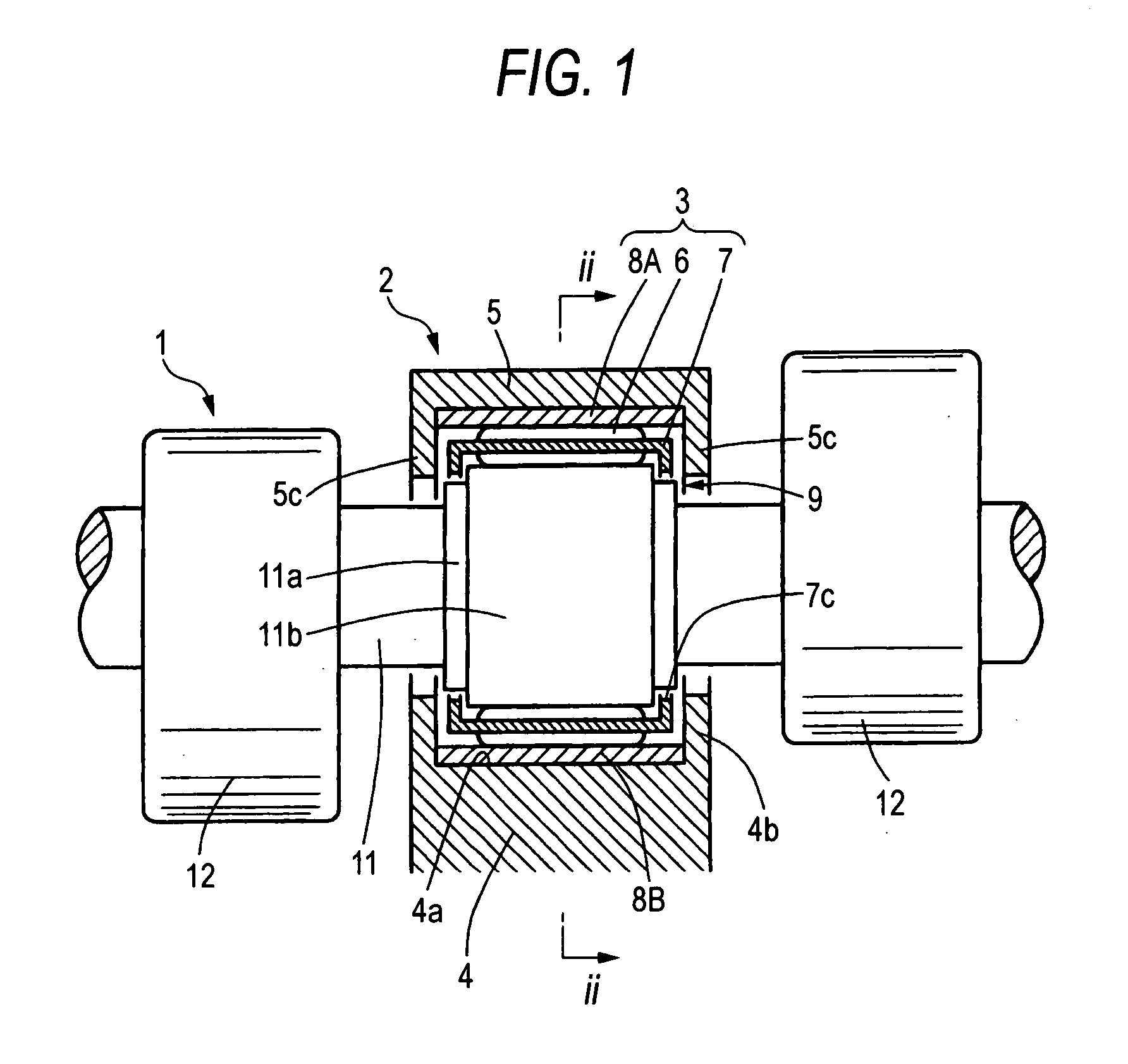
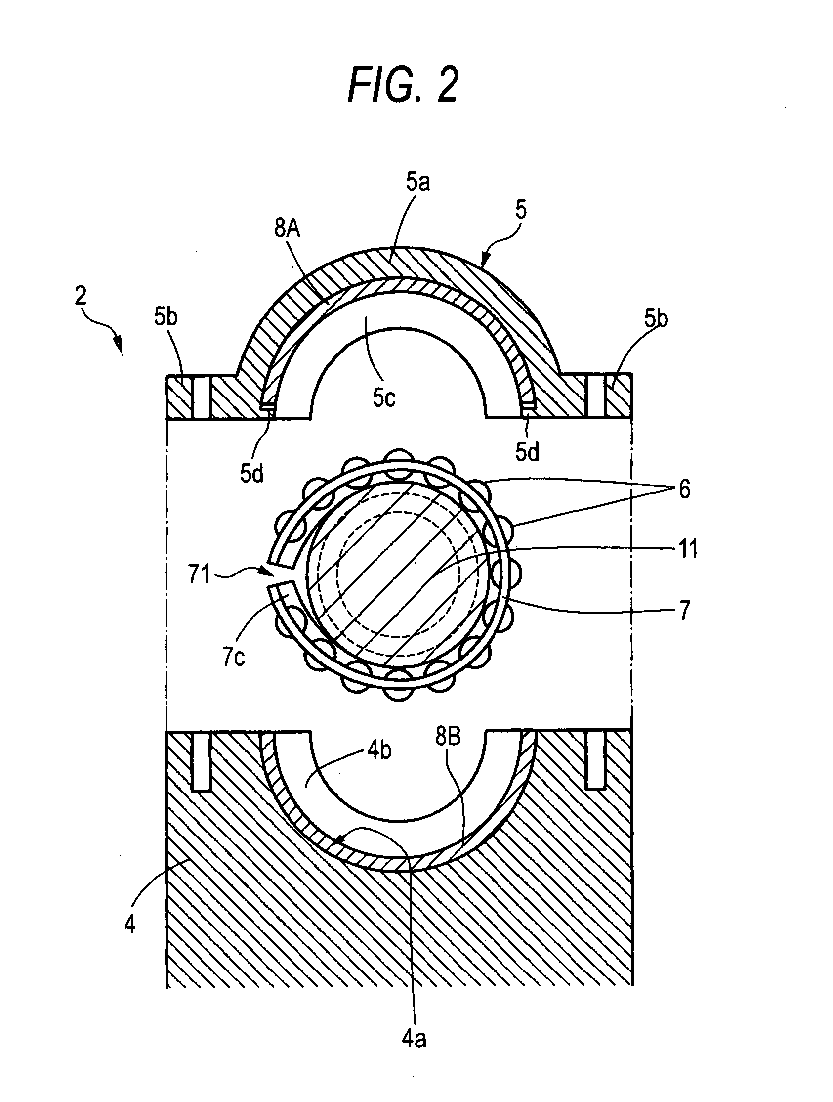
[0069] The outer ring split part 8A of the outer ring split parts 8A, 8B is fixed to the inner circumference of the arc portion 5a of the cam cap 5. as shown in FIG. 2, locking portions 5d are formed on the inner circumference at both circumferential ends of the arc portion 5a of the cam cap 5 and the circumferential ends of the outer ring split part 8A are locked into the locking portions 5d. Accordingly, the outer ring split part 8A is fixed to the inner circumference of the arc portion 5a of the cam cap 5.

[0070] The other outer ring split part 8B is mounted in an arc-shaped recess 4a formed on the housing 4. Similar to the cam cap 5, inner ribs 4b are formed at both axial sides of the arc-shaped recess 4a of the housing 4, radially protruding inward.

[0071] The cage 7 of the roller bearing 3 is formed of an elastic material, such as a resin, and as shown in FIGS. 2 and 3, has a cut 71 at only one circumferential position. A fitting protrusion 7a is formed at an end of the cut 71...

second embodiment

[0078] shown in FIGS. 4A and 4B, a cam cap 5 is made of a resin. An outer ring split part 8A has protrusions 8c that protrude radially outward from both circumferential ends. Protrusions 8d are formed at circumferential ends of the outer ring split part 8A by cutting and bending a portion of each of the protrusions 8c in the width direction. The outer ring split part 5A is integrally formed with a cam cap 5, so that it is fixed to the cam cap 5. According to the fixed configuration, it is possible to reduce the weight and cost because the cam cap 5 is made of a resin.

[0079] The protrusions 8d of the outer ring split parts 8A are formed for arrangement with an outer ring split part 8B disposed at the housing 4 and is fitted in recess (not shown) that are formed at axial ends of the outer ring split part BB at the housing 4. Further, when the outer ring split part 8A is integrally formed with the cam cap 5, the protrusions 8d is used to locate the outer ring split part 8A to a predet...

ninth embodiment

[0116] Similarly, in the embodiment shown in FIG. 18, attachment portions 27d are formed at an upper outer ring split part 27A, and not only the upper outer ring split part 27A, but a lower outer ring split part 27B are fixed to a housing 23, by fixedly attach the attachment portions 27d to the housing 23. It is the same as the ninth embodiment that a roller bearing 24 including the outer ring split parts 27A, 27B is fixedly mounted on the housing 23.

[0117] According to the embodiment shown in FIG. 18, since a cage 26 with rollers 25 held is axially restricted by the inner ribs 27o, 27p of the outer ring split parts 27A, 27B, as the ninth embodiment, a roller bearing 24 can be mounted around a portion having the same diameter as other portion of a shaft body 31 or a larger diameter portion 31b of the shaft body 31, without mounting the roller bearing 24 around an outer circumference of a smaller diameter portion 31a of the shaft body 31. Further, when the outer circumference of the ...


PUM


Abstract

A split roller bearing device of the invention includes a roller bearing of which at least the outer ring is separated into a plurality of split parts and a cap member that fixes the outer ring of the roller bearing between the body shaft and a housing and the outer ring split part is fixed inside the arc-shaped recess of the cap member.

Description

BACKGROUND OF THE INVENTION [0001] 1. Field of the Invention [0002] The present invention relates to a split roller bearing device that is disposed at a shaft support part mainly for a camshaft or a crankshaft in the engine of a vehicle. [0003] 2. Related Art [0004] Recently, it is further required for the engine of vehicles to reduce fuel consumption. It is needed to reduce energy loss at mechanical parts in the engine to reduce fuel consumption. [0005] In the related art, in the engines of vehicles, a camshaft is generally supported by a sliding bearing (e.g. see JP-A-11-148426); however, when a ball bearing is disposed at the shaft support part, instead of the sliding bearing, it has an effect on reducing the above-mentioned energy loss. According to estimates, when the engine operated under a specific condition (oil temperature: 40° C. and number of revolutions: 300 rpm) with the sliding bearing and the ball bearing equipped, torque was reduced by 1% when the ball bearing was us...

Claims


Application Information

Patent Timeline
Patent Type & Authority Applications(United States)
IPC IPC(8): F16C43/04
CPCF01L1/047F01L1/053F16C33/60F16C19/44F01L2001/0476F16C35/067F16C19/463F16C19/466F16C33/4694F16C33/581F16C35/042F16C2360/18
Inventor WASEDA, YOSHITAKAOKUMURA, TSUYOSHI
Owner JTEKT CORP
Why Eureka
Try Eureka