Receiver circuit

a receiver circuit and receiver technology, applied in the field of double conversion receiver circuits, can solve the problems of reducing the sensitivity of the receiver and generating noise in the produced sound, and achieve the effect of improving the sensitivity of the receiver and reducing the bea

Inactive Publication Date: 2007-09-27
SANYO ELECTRIC CO LTD
View PDF4 Cites 10 Cited by
  • Summary
  • Abstract
  • Description
  • Claims
  • Application Information

AI Technical Summary

Benefits of technology

[0014]The present invention was devised in order to solve the aforementioned problems, it being an object thereof to minimize beats resulting from higher harmonic components that may be generated during the generation of the two local oscillating signals and to make improvements in the sensitivity of the receiver.

Problems solved by technology

When components of the frequency IF2 resulting from higher harmonic components are mixed into the signal SIF2, these components pass through a band-pass filter (BPF) 30, resulting in problems wherein beats or other noise are generated in the produced sound and the sensitivity of the receiver decreases.

Method used


Image

  • Receiver circuit
  • Receiver circuit
  • Receiver circuit

Examples


Embodiment Construction

[0018]An embodiment of the present invention will be described below with reference to the drawings.

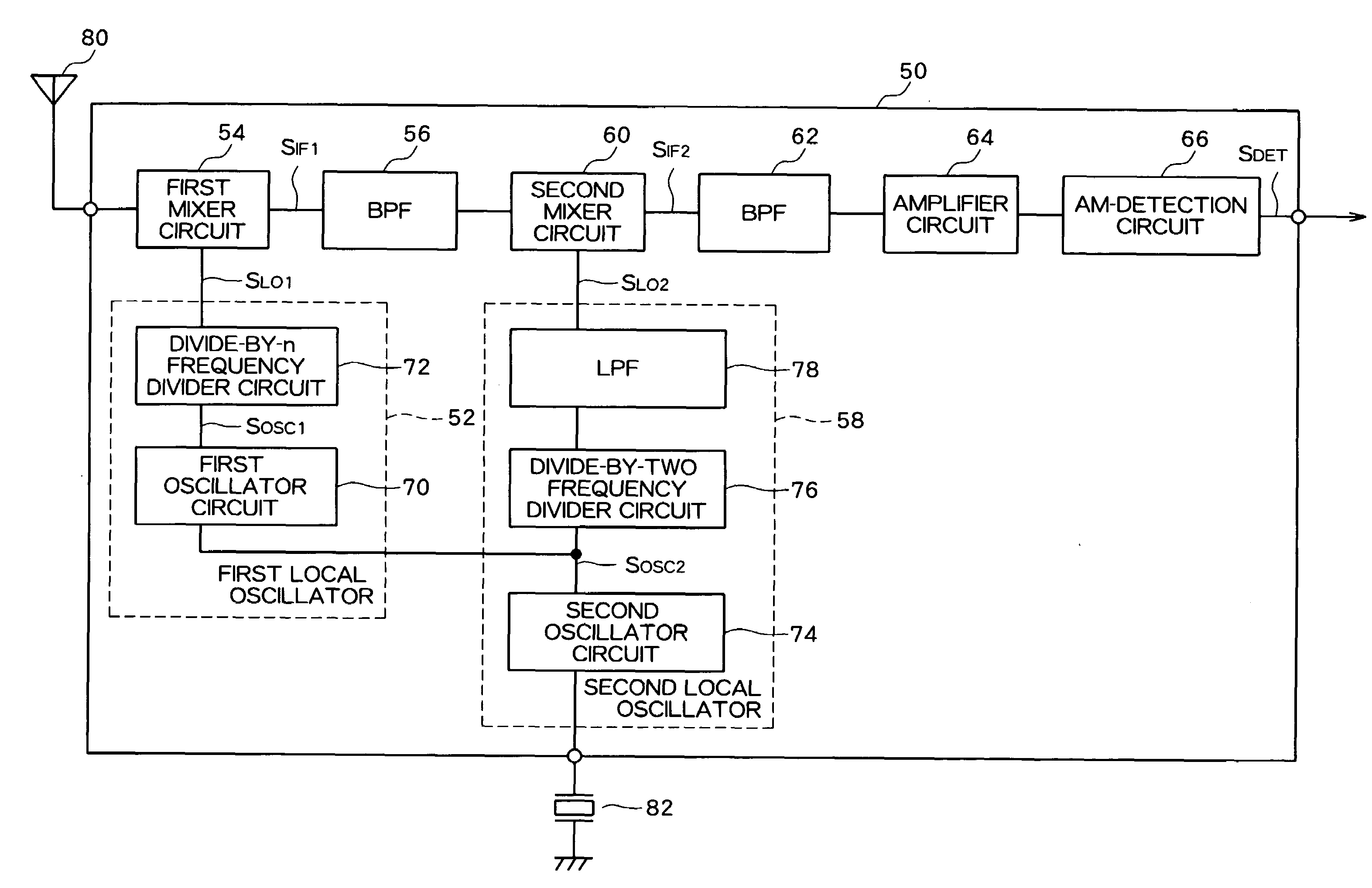
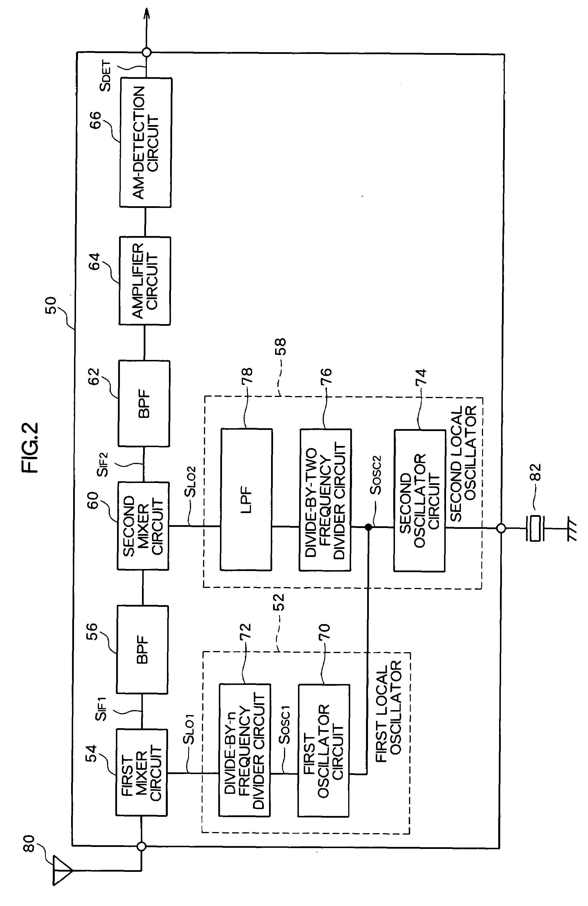
[0019]FIG. 2 is a block diagram that shows an abbreviated circuit configuration of a double-conversion AM-radio receiver that is an embodiment of the present invention. The main components of the receiver circuit are configured in an integrated circuit (IC) 50. A first local oscillator 52, a first mixer circuit 54, a BPF 56, a second local oscillator 58, a second mixer circuit 60, a BPF 62, an amplifier circuit 64, and an AM-detection circuit 66 are configured in the IC 50.

[0020]The first local oscillator 52 is configured to include a first oscillator circuit 70 and a divide-by-n frequency divider circuit 72. The second local oscillator 58 is configured to include a second oscillator circuit 74, a divide-by-two frequency divider circuit 76, and a low-pass filter (LPF) 78.

[0021]An RF signal SRF from an antenna 80 and an original oscillating signal S0 having a frequency f0 from a crysta...


PUM


Abstract

In double-conversion receiver circuits, higher harmonics of a first local oscillating signal SLO1 and higher harmonics of a second local oscillating signal SLO2 enter a mixing circuit that converts a first intermediate frequency IF1 into a second intermediate frequency IF2, resulting in problems in that frequency IF2 signal components that are generated by the mixture of the two signals cause decreased sensitivity. As a countermeasure, an LPF 78 is provided between a second mixer circuit 60 and a divide-by-two frequency divider circuit 76 that supplies the signal SLO2 to the second mixer circuit 60. The LPF 78 removes the higher harmonic components of the signal SLO2 that may be generated in the divide-by-two frequency divider circuit 76. Even when higher harmonic components of the signal SLO1 that may be generated in a divide-by-n frequency divider circuit 72 enter the second mixer circuit 60 through the semiconductor substrate and the like, the higher harmonic components of the second local oscillating signal SLO2 are not mixed in, and the occurrence of signal components of the frequency IF2 that result from higher harmonics being mixed in can thereby be prevented.

Description

CROSS-REFERENCE TO RELATED APPLICATION[0001]The priority application number JP2006-065925 upon which this patent application is based is hereby incorporated by the reference.FIELD OF THE INVENTION[0002]The present invention relates to a double-conversion receiver circuit that receives wireless transmission signals, and particularly relates to improved sensitivity.DESCRIPTION OF THE PRIOR ART[0003]Double-conversion circuit configurations for improving frequency selectivity in receivers for AM radio broadcasts and the like are well-known. FIG. 1 is a block diagram that shows the circuit configuration of a conventional double-conversion AM radio receiver. The main components of the receiver circuit are configured within an integrated circuit (IC) 2. A first mixer circuit 4 mixes a first local oscillating signal SLO1, which is output from a first local oscillator 6, and an RF (radio frequency) signal SRF that is obtained from an antenna 8, converting the frequency of the target receiver...

Claims


Application Information

Patent Timeline
Patent Type & Authority Applications(United States)
IPC IPC(8): H04B7/00
CPCH04B15/06H04B1/28H04B1/10
Inventor SUZUKI, JUN
Owner SANYO ELECTRIC CO LTD
Why Eureka
Try Eureka