Isolation list creation program, method, and device

Active Publication Date: 2007-09-27
FUJITSU LTD
View PDF1 Cites 4 Cited by
  • Summary
  • Abstract
  • Description
  • Claims
  • Application Information

AI Technical Summary

Benefits of technology

[0048] According to the present invention, firstly, maintenance of maser data of isolation devices which reach up to several hundreds of thousands can be performed. More specifically, since the present invention utilizes isolation lists which are created in the past as virtual master data, maintenance of isolation device master along with change of devices, which is required in a normal system, becomes unnecessary. In the case of a nuclear reactor plant, the isolation devices reach up to several hundred thousands; and, when the master is to be subjected to maintenance, an enormous amount of cost is taken; however, the maintenance cost can be drastically reduced. More specifically, in the case of the nuclear reactor plant, the master data is prepared through several times of periodical check in which the isolation lists are created.
[0049] Secondly, according to the present invention, an isolation list can be created without referencing many drawings. When an isolation list is to be created, many drawings such as system diagrams, sequence diagrams, and single line connection diagrams are referenced, a highlight pen is fully made use of to create the isolation list in the state close to manual operations, and this labor is enormous. On the other hand, according to the present invention, already-created isolation lists, which are past know-how and results, are automatically searched from the information of the master devices in an isolation range of a system diagram and displayed; as a resul

Problems solved by technology

However, in general nuclear reactor plants and plants of other industries, in many cases, the precondition that all the devices of plant equipment are categorized in the format of “device model-system-device” cannot be applied, the computer aid functio

Method used


Image

  • Isolation list creation program, method, and device
  • Isolation list creation program, method, and device
  • Isolation list creation program, method, and device

Examples


Embodiment Construction

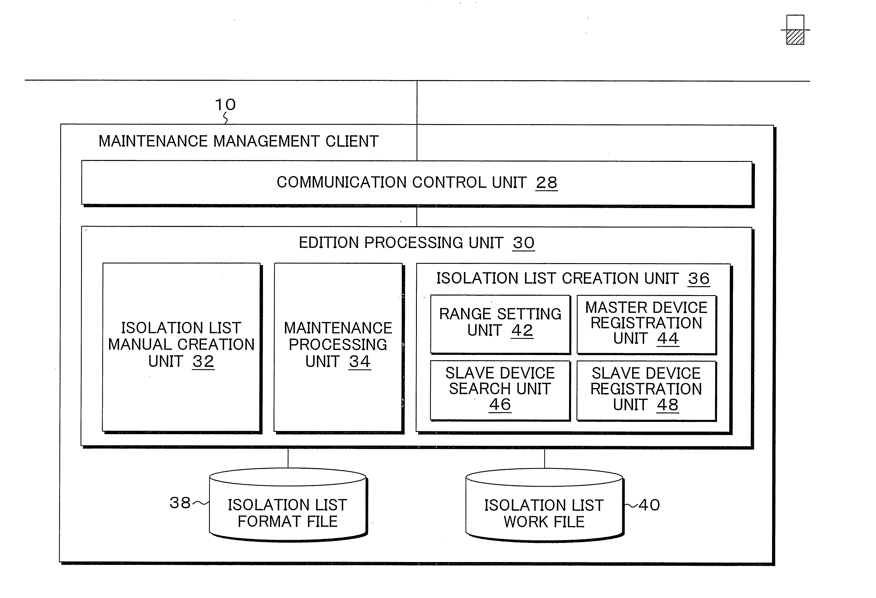
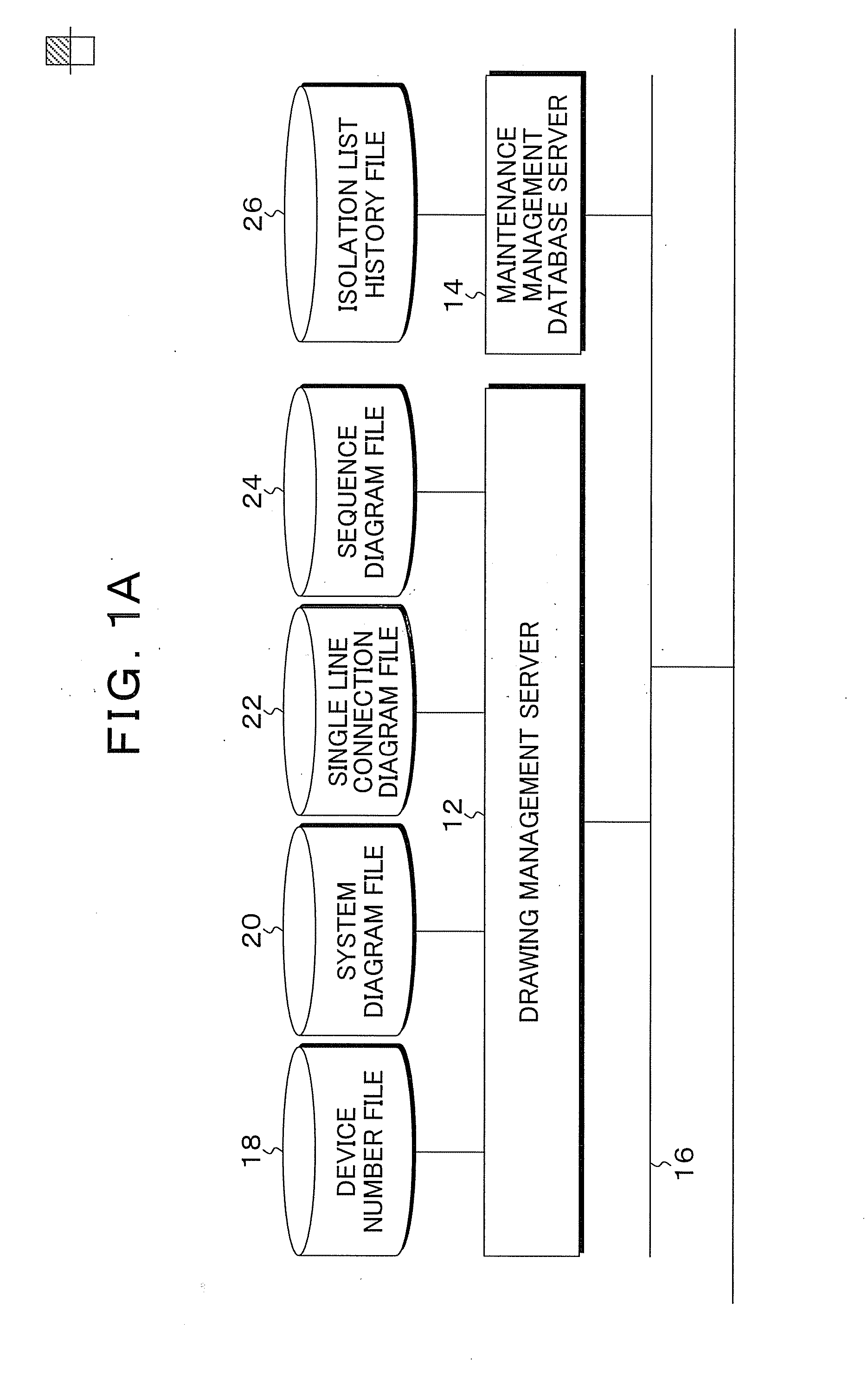
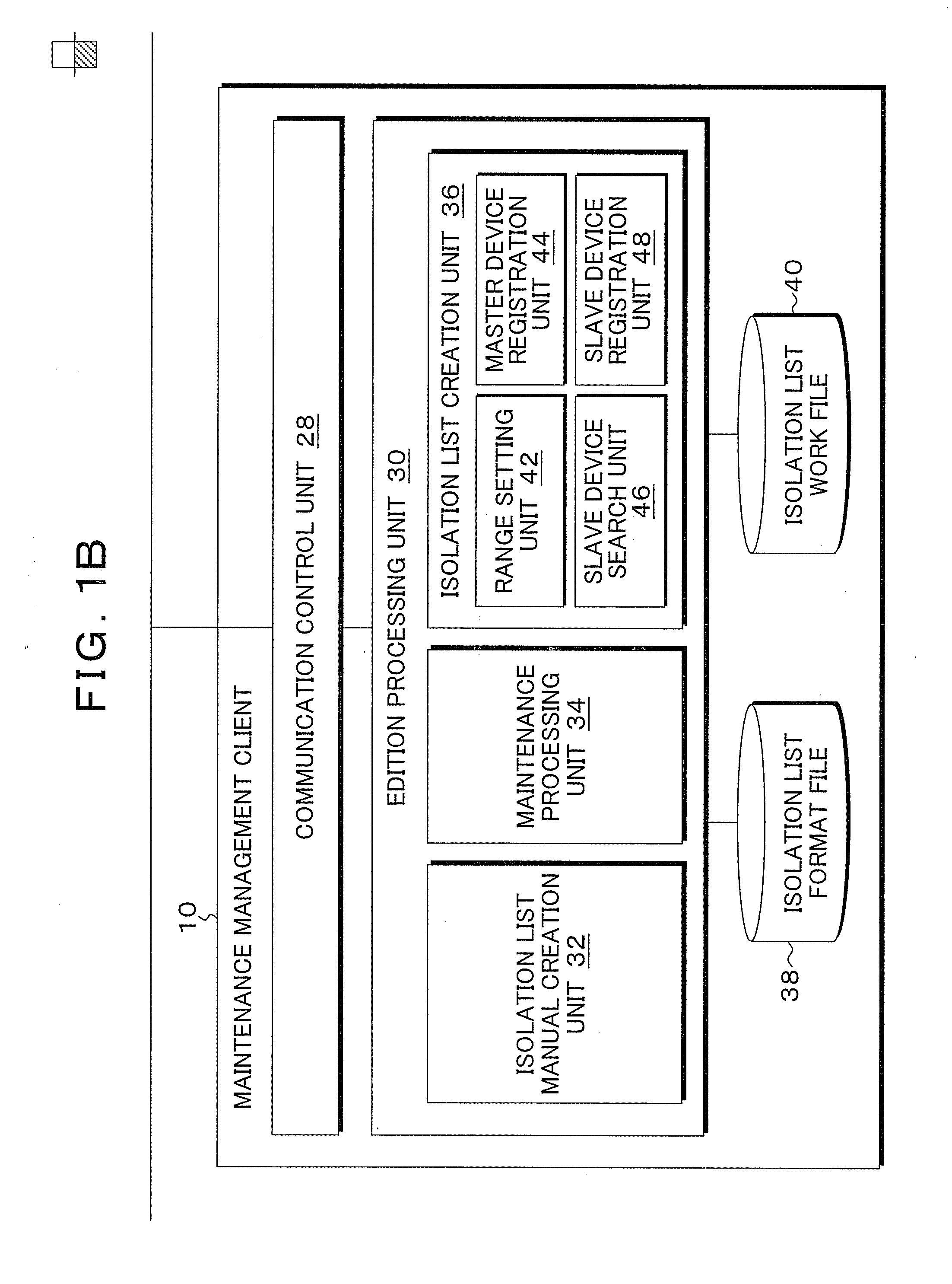
[0071]FIGS. 1A and 1B are block diagrams of a functional configuration of an isolation list creation device according to the present invention. In FIGS. 1A and 1B, the isolation list creation device of the present invention is installed in a maintenance management system which is provided for a plant such as a nuclear power plant; and, as a system configuration, with respect to a maintenance management client 10 which functions as the isolation list creation device of the present invention, a drawing management server 12 and a maintenance management database server 14 are connected via a network 16 such as a LAN.

[0072] To the drawing management server 12, drawing files such as a device number file 18, a system diagram file 20, a single line connection diagram file 22, and a sequence diagram file 24 are connected.

[0073] Also, to the maintenance management database server 14, an isolation list history file 26 is connected, wherein isolation lists created by manual operations and the...


PUM


Abstract

An isolation list containing information on a master/slave relation of isolation devices is stored in a history file. A range setting unit sets an isolation range according to a specifying operation with respect to the system diagram of equipment displayed on the screen. A master device registration unit extracts an isolation device present in the set range and registers it as a master device in the isolation list during editing. A slave device search unit successively selects a master device from the isolation list during editing, searches an isolation device which is in a relation of slave device with respect to the-selected master device from the history file, and displays a slave device list. A slave device registration unit inserts and places a slave device selected based on the selecting operation of the slave device list after the corresponding master device in the isolation list during editing, thereby completing the list.

Description

[0001] This application is a continuation of PCT / JP2005 / 023316, filed Dec. 20, 2004.[0002] This application is a priority based on prior application No. JP 2004-369140 filed Dec. 21, 2004, in Japan. TECHNICAL FIELD [0003] The present invention relates to isolation list creation program, method, and device which create an isolation list required in maintenance / check operations of plant devices with computer aid and, particularly relates to isolation list creation program, method, and device which create an isolation list efficiently and safely. BACKGROUND ART [0004] Conventionally, in a large scale plant such as a nuclear power plant, isolation operations which are system isolation operations in which fluids flowing in piping are blocked for a maintenance operation of the plant has been performed. An outline of the isolation operation is as the following. [0005]FIG. 17 is an example showing, on a screen, a part of plant equipment which is an object of the isolation operation, wherein...

Claims


Application Information

Patent Timeline
IPC IPC(8): G05B11/01G05B23/02G06Q50/00G06Q50/06
CPCY02E30/39G21D3/00Y02E30/00Y02E30/30
Inventor HASUNUMA, JUNICHIHAYASHI, HIROMIOOE, KIMIHIKOHAZAWA, HITOSHIKONNO, WATARU
Owner FUJITSU LTD
Why Eureka
Try Eureka