Electric power steering apparatus equipped with worm gear mechanism

a technology of worm gear and electric power steering, which is applied in the direction of gearing, hoisting equipment, transportation and packaging, etc., can solve the problems of reducing the worm gear transfer efficiency and reversing efficiency, worm gear and worm wheel gear are relatively difficult to manufacture, and require a relatively high manufacturing cost, so as to reduce the friction torque of the steering wheel caused by the motor friction torque, increase the reversing efficiency, and reduce the effect of steering wheel friction torqu

Inactive Publication Date: 2007-10-04
HONDA MOTOR CO LTD
View PDF2 Cites 29 Cited by
  • Summary
  • Abstract
  • Description
  • Claims
  • Application Information

AI Technical Summary

Benefits of technology

[0009]By not modifying the worm gear dedendum, it can work with the worm wheel gear addendum at low loads. Due to the contact at the dedendum of the worm gear tooth, the lead angle at the contact point is enlarged and transfer efficiency is increased. This tooth shape condition enables an increase in reversing efficiency in travel areas with low loads, such as when beginning the steering wheel turn and when turning the steering wheel back. Therefore, the friction torque of the steering wheel caused by the motor friction torque can be reduced and a favorable steering feeling can be provided to the electric power steering system.
[0010]On the other hand, as the working point is at the dedendum of the worm gear and the addendum of the worm wheel gear, the distance to the working point (contact point) is more extended for the worm wheel gear; therefore, loads can easily cause the worm wheel gear teeth to elastically deform. Even under these conditions of an increased load, the clearance between the worm gear modified in the negative direction and the worm wheel gear reduces, the t

Problems solved by technology

Due to the specially shaped tooth form employed, the worm gear and worm wheel gear are relatively uneasy to manufacture and require a relatively high manufacturing cost.
The small worm gear lead angle reduces the worm gear transfer efficiency and reversing efficiency,

Method used


Image

  • Electric power steering apparatus equipped with worm gear mechanism
  • Electric power steering apparatus equipped with worm gear mechanism
  • Electric power steering apparatus equipped with worm gear mechanism

Examples


Embodiment Construction

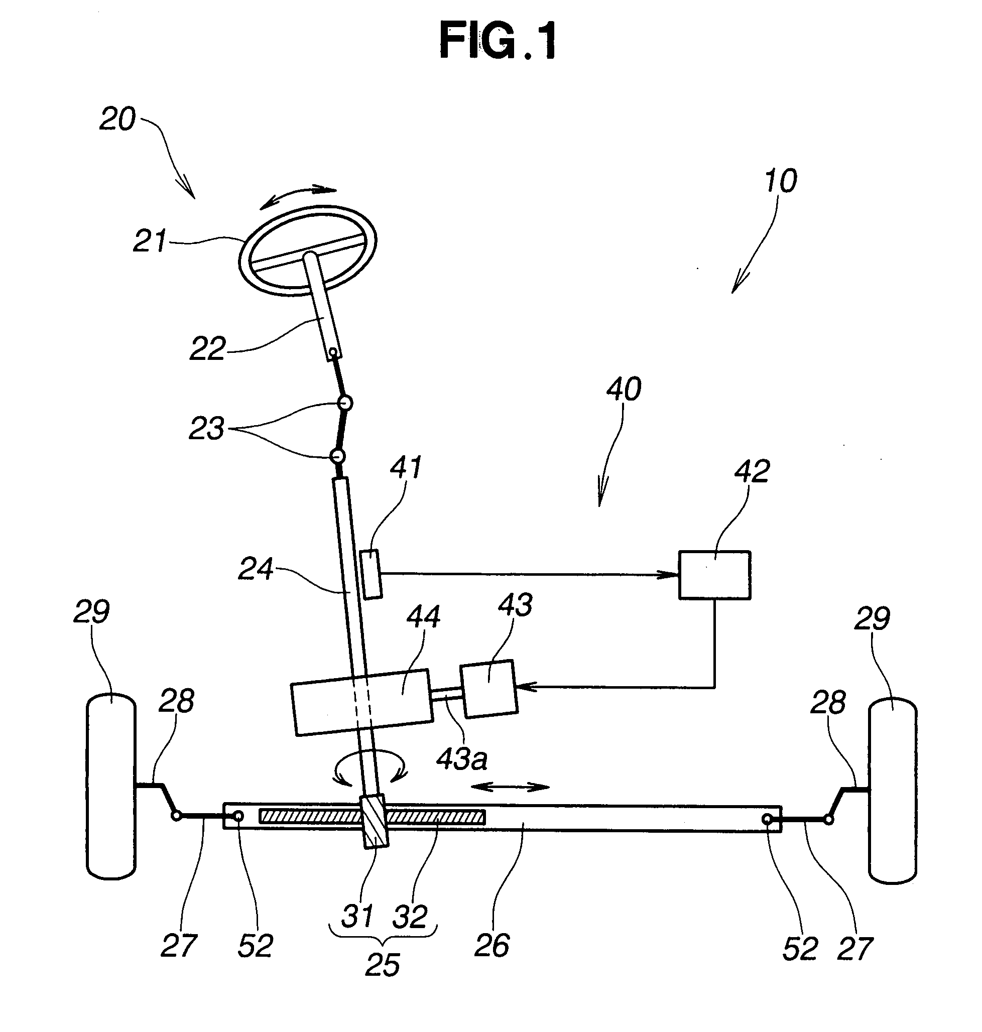
[0027]Referring now to the drawings and FIG. 1 is particular, there is shown an electric power steering apparatus equipped with a worm gear mechanism of the present invention.

[0028]The electric power steering apparatus 10 shown in FIG. 1 generally comprises a steering system 20 extending from a vehicle steering wheel 21 to steerable road wheels (in the illustrated embodiment, left and right front road wheels) 29 of the vehicle, and a steering torque assist mechanism 40 for supplying steering assist torque to the steering system 20.

[0029]In the steering system 20, a pinion shaft (input shaft) 24 is coupled to the steering wheel 21 via a steering shaft 22 and universal joints 23, and a rack shaft 26 is coupled to the pinion shaft 24 via a rack-and-pinion mechanism 25. Further, the left and right steerable road wheels 29 are coupled to opposite ends of the rack shaft 26 via left and right tie rods 27 and knuckle arms 28. The rack-and-pinion mechanism 25 includes a pinion 31 formed on t...


PUM


Abstract

An electric power steering apparatus includes a worm gear mechanism for transmitting the torque generated by an electric motor to a steered road wheel of the vehicle. The worm gear mechanism has a worm gear made of metal and a worm wheel formed of plastic material and meshing with the worm gear. The worm gear has a tooth profile including a dedendum part formed in an involute shape and an addendum part formed in a circular arc shape with a center located on a line of action.

Description

FIELD OF THE INVENTION[0001]The present invention relates to an electric power steering apparatus for motor vehicle of the type wherein motor torque generated in accordance with steering input is boosted using a worm gear mechanism and transferred to steerable road wheels to thereby reduce the driver's muscular steering effort.BACKGROUND OF THE INVENTION[0002]Electric power steering apparatus of the type concerned are known and used heretofore. In one such known apparatus, which is disclosed in Japanese Patent Laid-open Publication (JP-A) No. 2005-16617, a proposal has been made to enhance the wear durability of a worm gear mechanism by improving the lubricating performance using a worm gear and a worm wheel gear having a tooth form or profile in a special form, which is different from an involute form and can retain most part of a lubricating agent (grease) on tooth surfaces within the tooth width of the worm wheel gear. Due to the specially shaped tooth form employed, the worm gea...

Claims


Application Information

Patent Timeline
IPC IPC(8): F16H27/02
CPCB62D5/0409F16H55/06F16H55/22F16H55/24Y10T74/19828Y10T74/19623Y10T74/18792Y10T74/19953F16H55/283
Inventor WATANABE, KATSUJISHIMIZU, YASUO
Owner HONDA MOTOR CO LTD
Why Eureka
Try Eureka