
Balanced Rotary Engine

a rotary engine and balanced technology, applied in the direction of positive displacement engines, engines with rotating cylinders, reciprocating piston engines, etc., can solve the problems of reducing the effective chamber, affecting the combustion process, and not being suitable for mixture use, so as to achieve the effect of favoring the dissipation of heat generated during combustion

Inactive Publication Date: 2007-10-04
RUIZ MARTINEZ FRANCISCO JAVIER
View PDF6 Cites 5 Cited by
  • Summary
  • Abstract
  • Description
  • Claims
  • Application Information

AI Technical Summary

Benefits of technology

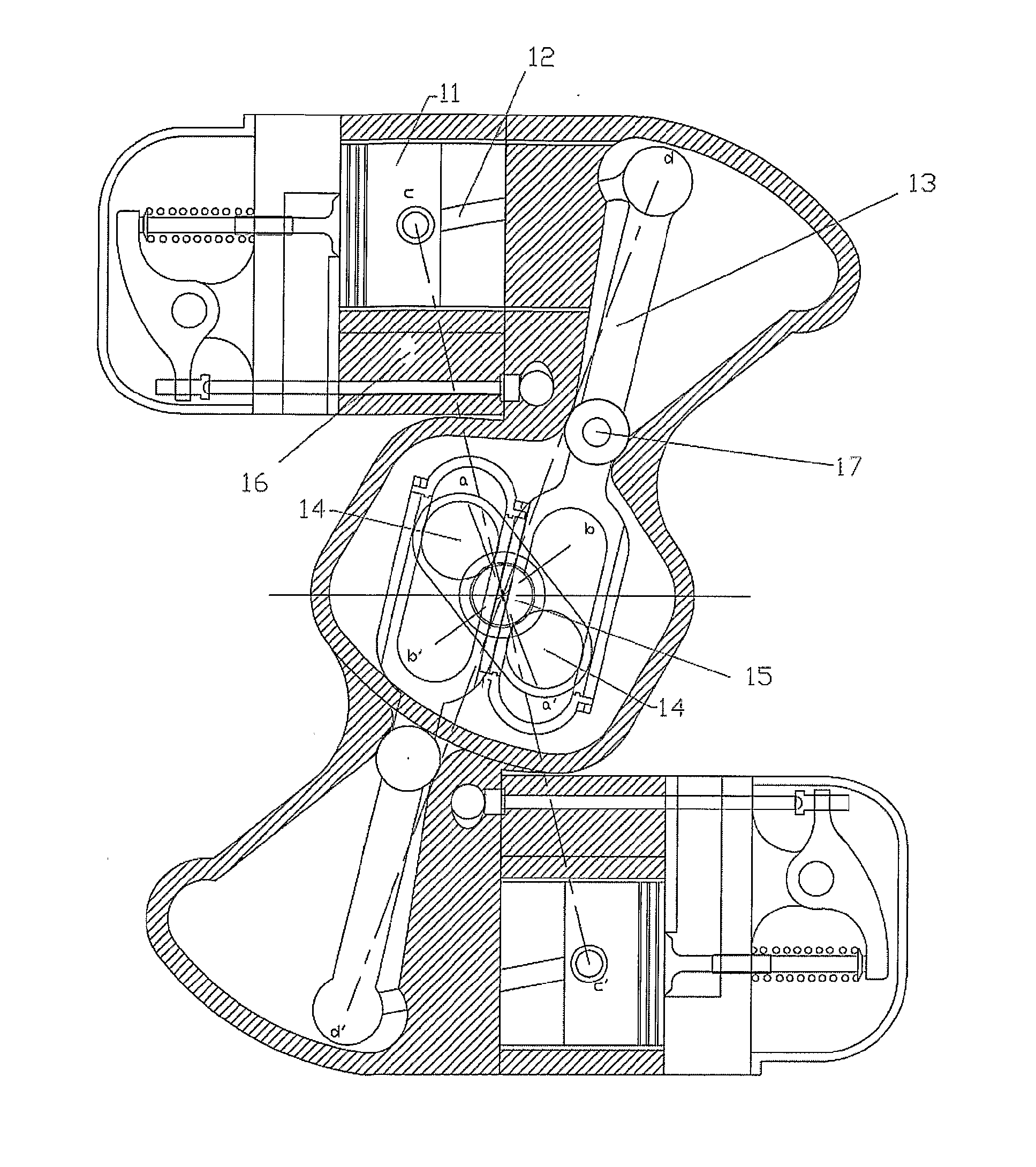
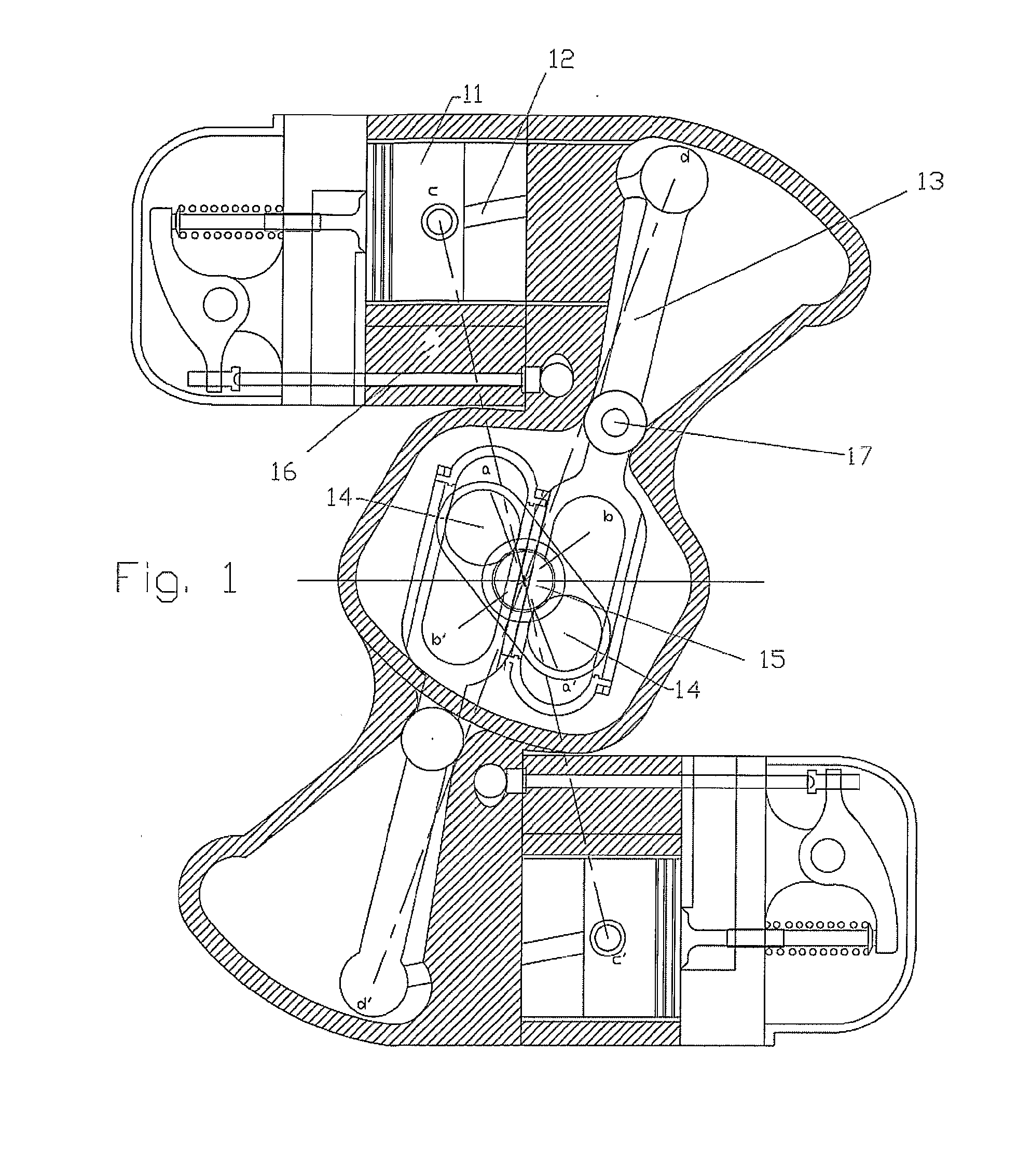
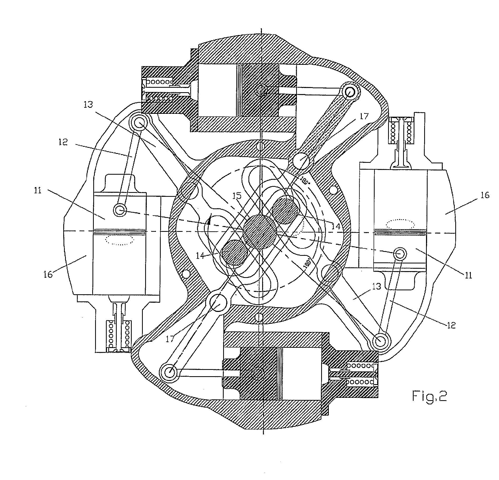
[0008] In the present invention, the pistons of each cylinder are coupled to a gudgeon of the crankshaft that is shifted the same number of degrees as the pistons and the chamber containing the inner elements is divided into several sealed compartments, a central compartment housing the crankshaft and the grooved part of the pivoted lever, and another outer chamber for each cylinder, with the piston, connecting rod and outer part of the pivoted lever separated by the rotating shaft thereof. This arrangement allows the individual powering of each cylinder subsequently facilitating the possible use thereof for two-stroke operations with a self-powering possibility.
[0011] The rotation of the block further favors the dissipation of heat generated during combustion.

Problems solved by technology

Two-stroke engines developed until now consist of the use of nozzles for the intake of the burning agent-fuel, which are made in the cylinder, which considerably reduces the effective chamber, the mixture inlet time, scavenging and compression of the engine, therefore it loses effectiveness and is not suitable for the use of mixtures which explode spontaneously.
Likewise, rotary engines consisting of tangential pistons currently under development have the opposing pistons coupled to the same gudgeon or journal of the crankshaft by means of which movement of the internal elements (pistons, connecting rods and pivoted lever) is not symmetrical during the rotation of the assembly, causing vibration-generating loads.
In the same way, these are housed in a single chamber, making their lubrication difficult when the agent used for this purpose moves to the outside thereof driven by centrifugal force.

Method used


Image

  • Balanced Rotary Engine
  • Balanced Rotary Engine
  • Balanced Rotary Engine

Examples


Embodiment Construction

[0023] As can be seen in the attached drawings, there are two preferred embodiments for the balanced rotary engine. The first embodiment shows a balanced rotary engine (FIGS. 1, 2 and 3) whereas the second embodiment shows a self-powered balanced rotary engine (FIGS. 4, 5, 6, 7, 8, 9 and 10).

[0024] In the balanced rotary engine, the pistons (11) (FIGS. 1, 2 and 3) are coupled by means of their connecting rods (12) and the pivoted lever (13), to a gudgeon (14) of the crankshaft (15), which is shifted the same number of degrees ads the cylinders (16), thus obtaining in its linear alternative shifting during the rotation of the assembly (the block with these elements rotates in one direction and the crankshaft in the other) that they remain permanently balanced, either due to the opposite one or as a whole, in the case of an engine with an odd number of cylinders (FIG. 3). This arrangement allows coupling (FIG. 2) two pistons (11) to the same gudgeon (14) of the crankshaft (15) provid...


PUM


Abstract

The invention relates to a balanced rotary engine consisting of a rotary engine comprising tangential pistons which improve engine performance, facilitate the lubrication of the engine components, enable the use thereof at high revolutions and condition same for two-stroke operation with full use of the combustion chamber, even with mixtures (diesel cycle) which explode spontaneously upon reaching high compressions with a suitable volume. According to the invention, the components are structured such that (i) the engine can also be self-powered and (ii) the air or mixture is drawn directly from the rear of the cylinder and, subsequently, injected into the combustion chamber of said cylinder or of the cylinder adjacent thereto.

Description

II. BACKGROUND OF THE INVENTION [0001] 1. Field of the Invention [0002] The present specification relates to a balanced rotary engine consisting of a rotary engine comprising tangential pistons which improve engine performance, facilitate the lubrication of the engine components, and enable the use thereof at high revolutions. The components are structured such that the engine can also be self-powered and the air or mixture is drawn directly from the rear of the cylinder and, subsequently, injected into the combustion chamber of said cylinder or of the cylinder adjacent thereto, and they condition same for two-stroke operation with full use of the combustion chamber, even with mixtures (diesel cycle) which explode spontaneously upon reaching high compressions with a suitable volume. [0003] 2. Description of the Related Art [0004] Two-stroke engines developed until now consist of the use of nozzles for the intake of the burning agent-fuel, which are made in the cylinder, which consid...

Claims


Application Information

Patent Timeline
Patent Type & Authority Applications(United States)
IPC IPC(8): F01B13/04F01B5/00F01B9/02F01B9/08F02B75/02F02B75/26
CPCF01B5/006F01B9/023F02B2075/025F02B75/265F01B9/08
Inventor RUIZ MARTINEZ, FRANCISCO JAVIER
Owner RUIZ MARTINEZ FRANCISCO JAVIER
Learn More