Photovoltaic module

a photovoltaic module and photovoltaic technology, applied in the direction of pv power plants, light radiation electric generators, generators/motors, etc., can solve the problems of reducing the efficiency of the module, reducing the yield of the manufacturing process, and generating air bubbles, so as to reduce the area occupied, prevent the generation of air bubbles, and improve the module efficiency

Active Publication Date: 2007-10-04
SANYO ELECTRIC CO LTD
View PDF7 Cites 21 Cited by
  • Summary
  • Abstract
  • Description
  • Claims
  • Application Information

AI Technical Summary

Benefits of technology

[0026]The present invention can reduce the area occupied by the interconnectors. It improves the module efficiency by arranging the interconnectors on the rear surface side of the solar cell.
[0027]The interconnectors are thin and arranged so as not to overlap each other. It prevents the air bubbles from generating. Since the interconnectors are wide and formed, the pressing strength applied under reduced pressure can be widely dispersed over the solar cell, thereby preventing the solar cell from cracking due to the stress concentration.
[0028]By using a metal foil coated with a laminated film having self-adhesiveness for the interconnectors, the insulator or the like can be fixed and the unit or the like can be temporarily fixed. Therefore, the photovoltaic module can be easily assembled.
[0029]Additionally, the interconnectors can have further increased width by alternately reversing the polarity of the solar cells of the adjacent units. It reduces the interconnector resistance.

Problems solved by technology

The aforementioned photovoltaic module has a problem that the module efficiency is lower due to an area which is not contributory to power generation occupied by the interconnectors.
When the interconnectors located at the periphery have an increased thickness or an overlapping part of these interconnectors is existed, it causes a generation of air bubbles when laminating.
Then, the generation of air bubbles reduces the yield of manufacturing process.

Method used


Image

  • Photovoltaic module
  • Photovoltaic module
  • Photovoltaic module

Examples


first embodiment

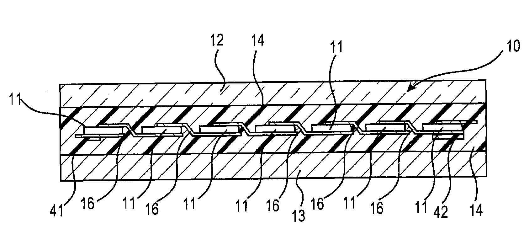
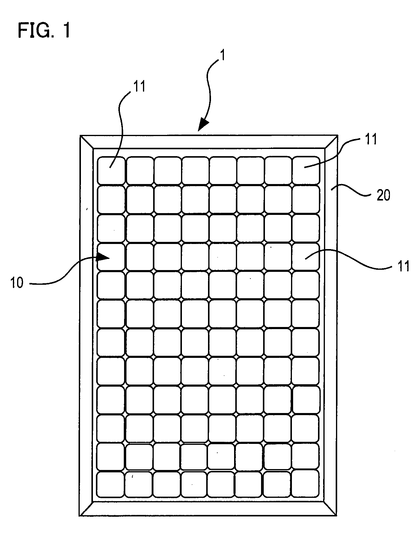
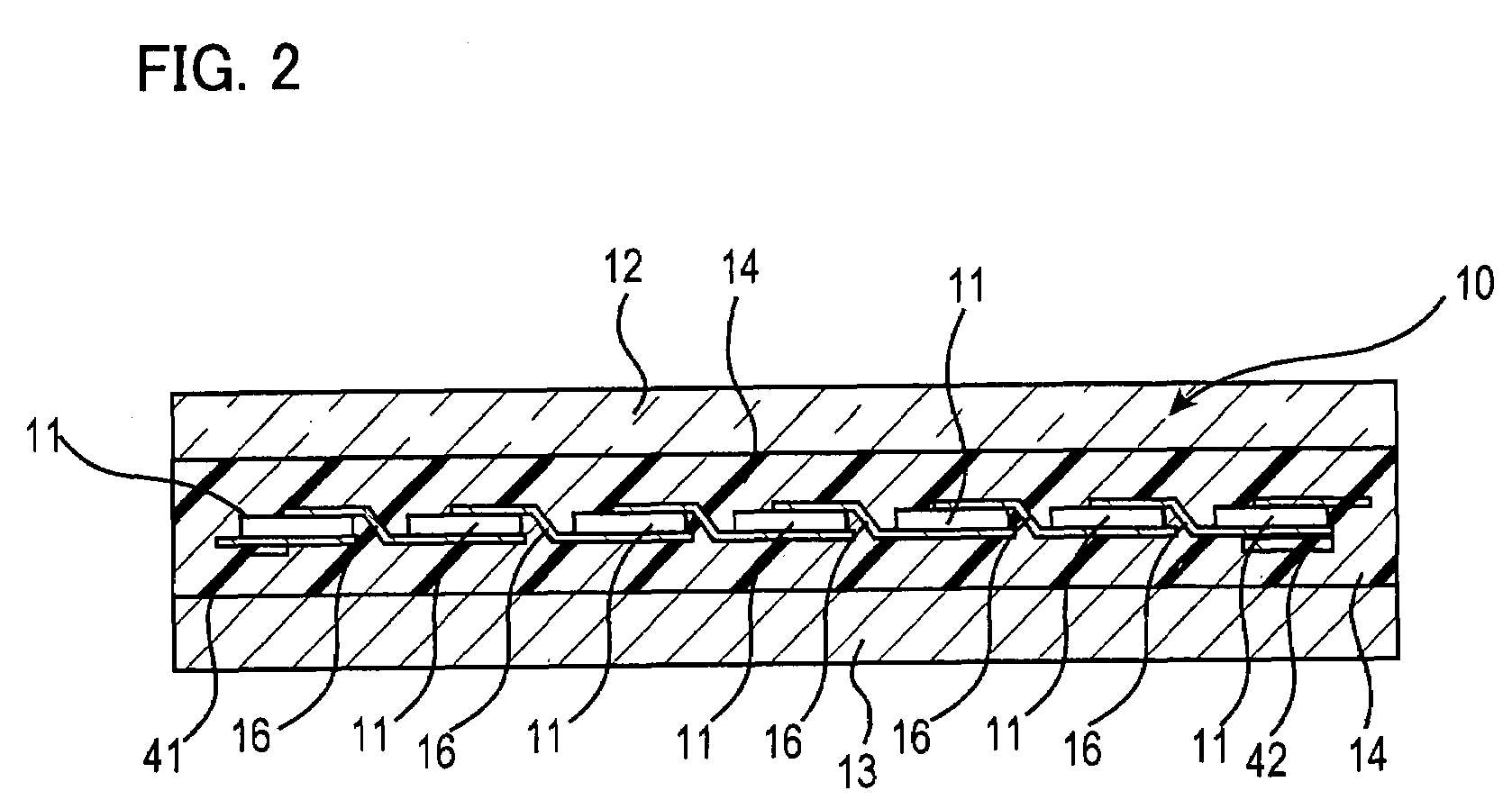
[0062]In the first embodiment as illustrated in FIG. 4, twelve solar cells 11 (the solar cells positioned in between are not shown in the figure) are connected in series through the tab connectors 16 so as to form a unit (strings 40). In the embodiment, eight such strings 40 are connected in series. In the photovoltaic module 1, the solar cells 11 are arranged in twelve series and in eight lines. This invention is also applicable, even though the number of series is increased or reduced, which means that the number of the solar cell 11 of the strings 40 is increased or reduced.

[0063]In the embodiment, the strings 40 are arranged so that p-type amorphous silicon layer 113 side of the solar cell 11 faces light-receiving surface side and the adjacent solar cells 11, 11 are interconnected through the tab connectors 16. The tab connector 16 has one end connected to collector electrode on a upper surface side of a given solar cell 11 and the other end connected to collector electrode on a...

second embodiment

[0089]FIGS. 7 and 8 are schematic cross-sectional views of the photovoltaic module according to the present invention illustrating each strings connected through the interconnectors.

[0090]In FIGS. 7 and 8, solar cells 11a, 11b have same basic structure as that shown in FIG. 3. For example, the solar cell 11a is a cell used for arranging so that the p-type amorphous silicon layer 113 side faces to the light-receiving side, and the solar cell 11b is a cell used for arranging so that the n-type amorphous silicon layer 119 side faces to the light-receiving side.

[0091]The each solar cells 11a, 11b with such arrangement have predetermined a film thickness, a film material, and the like for optimal conversion efficiency.

[0092]As illustrated in FIGS. 7 and 8, the solar cells 11a and the solar cells 11b can be connected in series by alternately arranging the solar cells 11a and the solar cells 11b and connecting with each collector electrodes through tab connectors 16a, 16b. The negative ele...

third embodiment

[0096]In the aforementioned embodiment shown in FIG. 4, since the copper foil of the lead-out wire 42a, 43a of the interconnector 42, 43 are thin and formed, there is undeniably an increased resistance. While, in the third embodiment shown in FIG. 11, the leading-out part of the interconnector 42 connecting to the negative electrode and the positive electrode is remained wide so as to lead out to the terminal box 30.

[0097]In the third embodiment shown in FIG. 11, the interconnector 41 has an increased width and the connection 44b connecting with the tab connector of the interconnector 44 has an increased width. Therefore, the interconnectors 41, 44 and the interconnectors 42, 43 are partially and slightly protruded outside the solar cell 11. Then, the terminal box 30 is made large in a vertical direction, and a position where the lead-out wire connecting to the terminal box is inserted is moved to the upper edge side. Such structure can prevent the resistance increase. Although the ...


PUM


Abstract

It is an object of the present invention to provide a photovoltaic module capable of reducing an area occupied by interconnectors. The photovoltaic module of the present invention comprises light-transmitting substrate, strings including a plurality of solar cells interconnected through tab connector, and rear surface member. A plurality of the strings is electrically connected through interconnectors and arranged on a rear surface side so as not to overlap each other. The photovoltaic module is sealed with a sealant between the light-transmitting substrate and the rear surface member.

Description

[0001]The priority applications Numbers JP2006-99978 and JP2007-27067, upon which this patent application is based are hereby incorporated by reference.BACKGROUND OF THE INVENTION[0002]1. Field of the Invention[0003]The present invention relates to a photovoltaic module, and more particularly, to a photovoltaic module in which a plurality of solar cells is sealed with a sealant between a light-transmitting substrate and a rear surface member.[0004]2. Description of Related Art[0005]From the viewpoint of global environment, attention is being given to solar cells that can convert light from the sun, which is a clean inexhaustible energy source, directly into electricity.[0006]Because a single solar cell outputs as small as a few watts, generally a plurality of solar cells is electrically connected in series to enhance the output to a few hundreds watts and used as a photovoltaic module to power houses and buildings.[0007]The conventional photovoltaic module will be descried according...

Claims


Application Information

Patent Timeline
Patent Type & Authority Applications(United States)
IPC IPC(8): H02N6/00
CPCH01L31/048Y02E10/52Y02E10/50H01L31/0201H01L31/0504H01L31/05H01L31/0508
Inventor NAKAJIMA, TAKAAKINAKATANI, SHIHOMIOKAMOTO, SHINGO
Owner SANYO ELECTRIC CO LTD
Why Eureka
Try Eureka