Centering process in chucking work and apparatus therefor

Active Publication Date: 2007-10-04
NIPPON THOMPSON
View PDF1 Cites 9 Cited by
  • Summary
  • Abstract
  • Description
  • Claims
  • Application Information

AI Technical Summary

Benefits of technology

[0010]The present invention, therefore, has as its primary object to solve the major challenges as described just above and to provide a process and an apparatus for centering a workpiece in a machine tool including a lathe and so on, which has a work spindle with a chuck thereon used for processing, turning, facing and inspecting operations applied on a workpiece having a circular part. More particularly, the present invention provides a process and an apparatus for centering a workpiece having a circular part, in which the centering operation to set the workpiece on the chuck by virtue of magnetic or vacuum attraction with the center of the workpiece lying in alignment with the rotational axis of the chuck can be achieved by just installation of a centering tool that is simple in construction. Thus, the process and apparatus for centering a workpiece constructed as stated earlier according to the present invention makes it easier to perform the centering operation in chucking work more accurately and rapidly in diverse working fields including processing, measuring and so on of the workpiece, thereby improving the working efficiency in the processing, turning, facing, measuring operations.
[0015]The centering process and apparatus constructed as recited earlier can be well applied to a wide variety of machines. Just mounting the centering tool of simple construction to any moving part of a turret of machine tools is sufficient to perform quickly the centering operation to set the center of the workpiece in alignment with the rotational center of the chuck, such as magnet chuck and vacuum chuck, on which the workpiece having a circular part is attracted for cuts, such as turn and face, and measurements. High-speed centering of the workpiece on the chuck is desirable to complete the cuts including turning of inside and outside circular surfaces, facing flat surfaces on the ends of the cylindrical workpiece with high efficiency.

Problems solved by technology

The processor constructed as stated earlier, nevertheless, has need of a carriage to carry the loose headstock thereon, and therefore could not get out of becoming bulky in construction.
Moreover, the workpiece held in the three-jaw chuck, as deformed easily as shown in FIG. 9, is unfair disadvantageous to the centering operation and therefore poses an issue of causing variations in centering from one work to another.
With the prior automatic centering process, thus, there are practical issues that the machine tool has to be made bulky in construction and also lacks in universality for a variety of workpiece size.
The prior centering device constructed as stated earlier needs to set the stoppers with high accuracy in their locations and also lacks in universality for wide variations in circular plate size.
However, the centering apparatus for the circular plate in which the four pads are arranged to embrace the circular plate would have a margin of error because the four pads doing their works on the circular plate could vary from one pad to another pad in working position.
Moreover, the machine tool has to be made bulky in construction.

Method used


Image

  • Centering process in chucking work and apparatus therefor
  • Centering process in chucking work and apparatus therefor
  • Centering process in chucking work and apparatus therefor

Examples


Embodiment Construction

[0025]A preferred embodiment of a process and an apparatus for centering a workpiece according to the present invention will be explained hereinafter in detail with reference to the accompanying drawings. The present invention is preferably adapted to a centering process and apparatus for a workpiece, which is used in a diversity of machines including machine tools, inspection instruments, measuring instruments, semiconductor fabricating equipment, various robots, and so on.

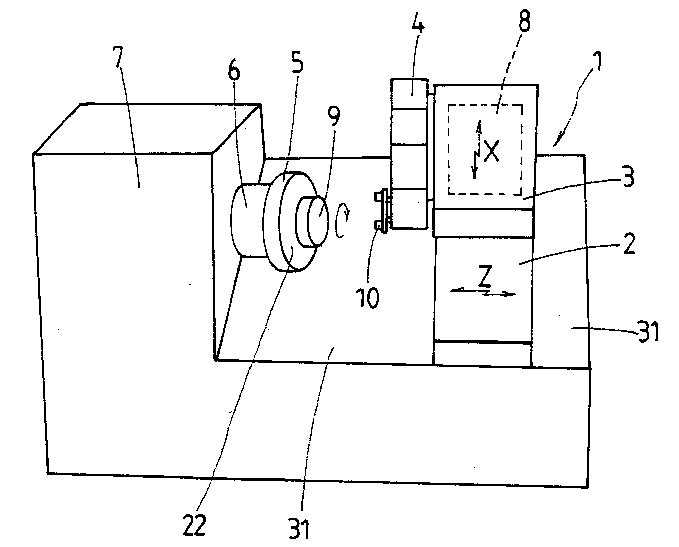
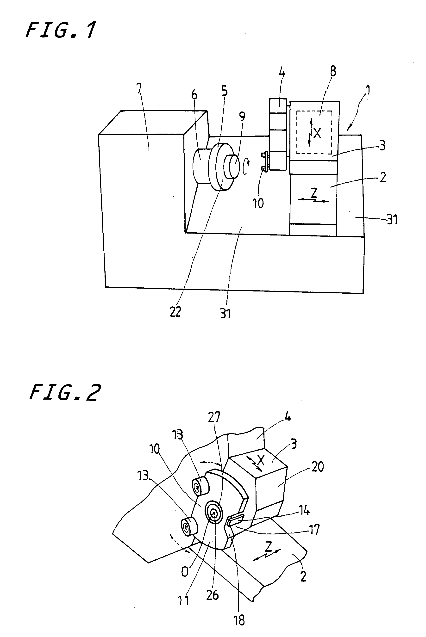
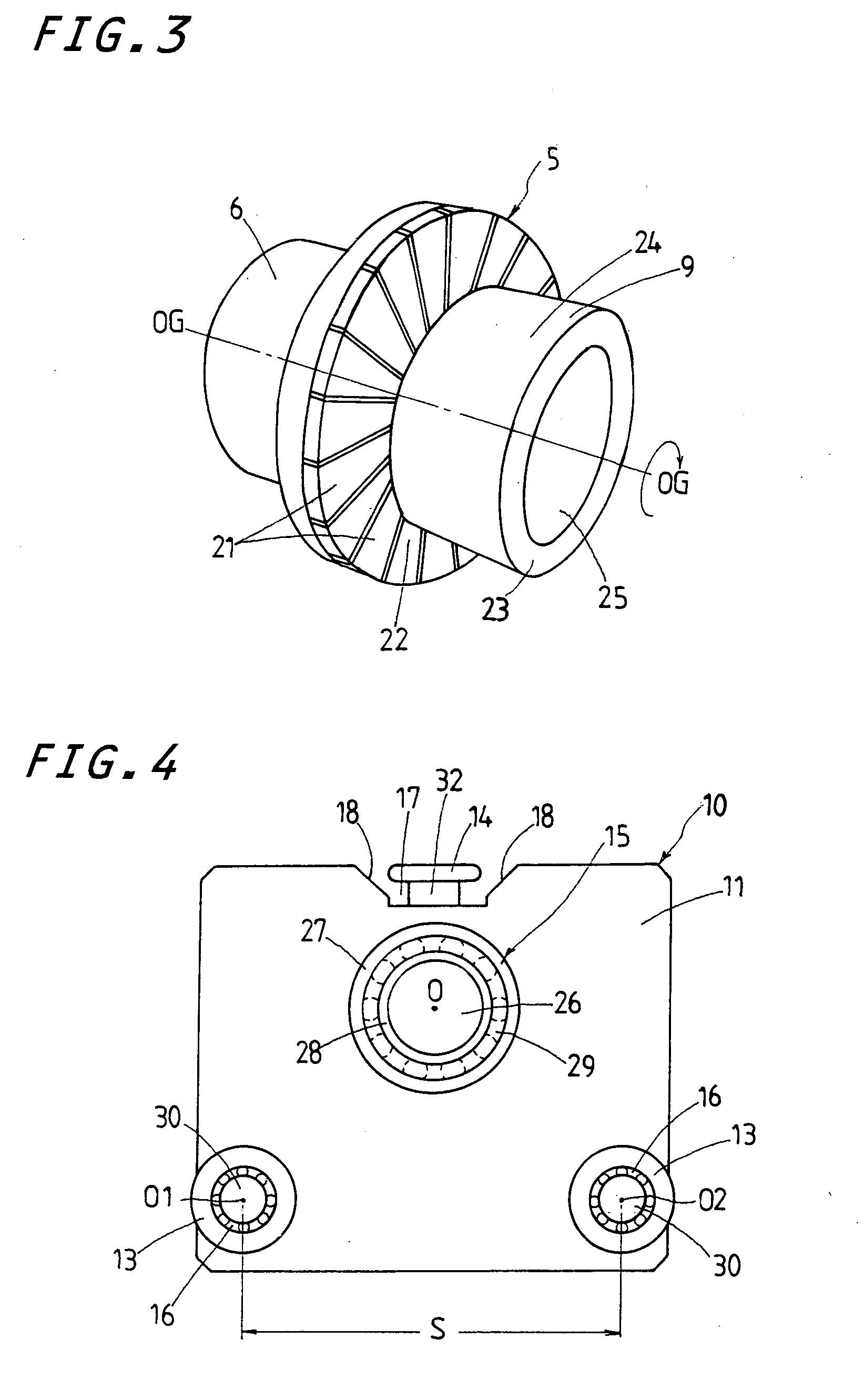
[0026]The embodiment of the centering apparatus according to the present invention is shown in FIGS. 1 to 3 in a fashion adapted for a machine tool 1 or lathe of the type equipped thereon with a magnet chuck 5 of circular contour. The magnet chuck 5 is composed of many permanent magnet pieces 21 whose flat front surfaces serve as attractive surfaces 22. The magnet pieces 21 are positioned circularly around a work spindle 6 in a fashion extending radially outward of the work spindle 6 and revolving together with t...


PUM


Abstract

A process and apparatus for centering accurately and speedy a workpiece on a magnet chuck mounted on a work spindle. A pair of action pads spaced away from one another comes into engagement with the workpiece attracted to the work spindle, thereby performing the centering operation. The action pads are mounted on a support plate that can freely turn on a fulcrum. As the fulcrum makes head towards a rotational center of the magnet chuck, the action pads comes into abutment in a rocking manner against the workpiece that is held at off-center relation in the chuck, thereby compensating the off-center relation to keep a center of the workpiece in alignment with the rotational center of the chuck.

Description

FIELD OF THE INVENTION[0001]The present invention relates generally to a machine tool including a lathe and so on having a work spindle equipped thereon with a magnetic chuck and, more particularly, to a process for centering a workpiece in a chucking phase on a chuck mounted on the machine spindle and an apparatus therefor.BACKGROUND OF THE INVENTION[0002]There are conventionally known processors that can perform accurate facing operations with no need of centering work on a hollow cylindrical workpiece. One example of the processors of the sort as stated just earlier is disclosed in Japanese Patent Laid-Open No. 2002-337012, which is envisaged turning a workpiece of material heat-treated to be highly hardened. The prior processor is composed of a machine spindle supported for rotation on a headstock fastened on a machine bed, a magnet chuck mounted on a lengthwise end of the machine spindle in a way revolving coaxially with the machine spindle, a loose headstock placed on the same...

Claims


Application Information

Patent Timeline
IPC IPC(8): B23B31/28
CPCB23B13/12B23B2270/12B23Q3/183Y10T279/26B23Q3/152Y10T279/29Y10T279/23B23Q2230/002
Inventor KOSHINO, NAOKI
Owner NIPPON THOMPSON
Why Eureka
Try Eureka