System for Using Larger Arc Lamps with Smaller Imagers

a technology of imagers and arc lamps, applied in the field of multi-imager projection systems, can solve problems such as difficulty in reducing the amount of light in the dark state, difficulty in providing outstanding contrast ratios, and contouring artifacts, and achieve the effect of improving the contrast and contouring of light signals, and improving the quality of video pictures

Inactive Publication Date: 2007-10-04
THOMSON LICENSING SA
View PDF9 Cites 26 Cited by
  • Summary
  • Abstract
  • Description
  • Claims
  • Application Information

AI Technical Summary

Benefits of technology

[0010] The invention provides a projection system that provides improved contrast and contouring of a light signal on a pixel-by-pixel basis using a two-stage projection architecture, thus improving all video pictures. The projection system uses two imagers, the first being larger to accommodate a large lamp, sized to the first imager and the second being smaller. The first imager has a matrix of pixels for modulating light on a pixel-by-pixel basis to form a first modulated matrix of light. The second imager has a matrix of pixels corresponding to the pixels of the first imager for modulating the first modulated matrix of light on a pixel-by-pixel basis to form a second modulated matrix of light. The second imager having a size smaller than the size of the first imager. A relay lens set provides a magnification of less than 1.0 to relay each pixel of light in the first modulated matrix of light onto a corresponding pixel of the second imager.

Problems solved by technology

One of the major disadvantages of existing LCOS and DLP systems is the difficulty in reducing the amount of light in the dark state, and the resulting difficulty in providing outstanding contrast ratios.
This is, in part, due to the leakage of light, inherent in these systems.
This can lead to contouring artifacts.
This improves some pictures, but does little for pictures that contain high and low light levels.
Reducing the imager area places increasing constraints on the arc lamp design.
The reduction in size of the arc lamp results in increasingly shorter arc lamp life, causing increased maintenance and cost to operate the microdisplay.

Method used


Image

  • System for Using Larger Arc Lamps with Smaller Imagers
  • System for Using Larger Arc Lamps with Smaller Imagers
  • System for Using Larger Arc Lamps with Smaller Imagers

Examples


Embodiment Construction

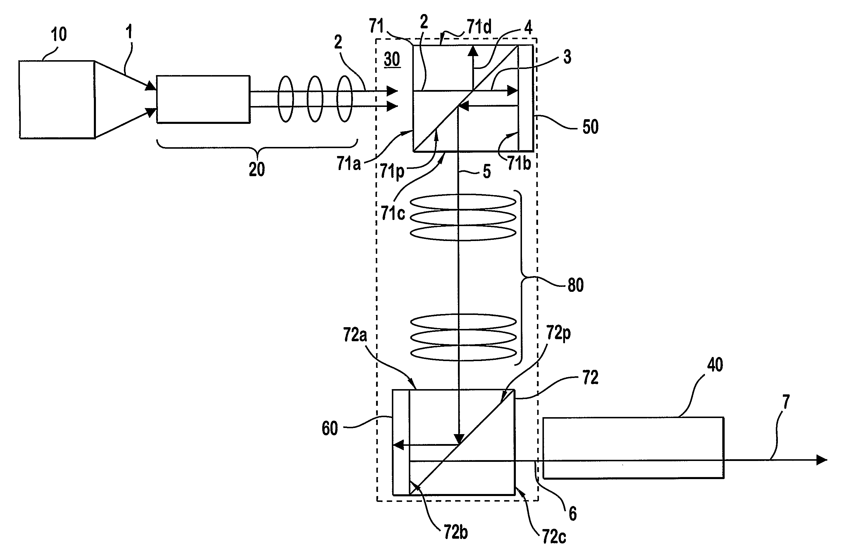
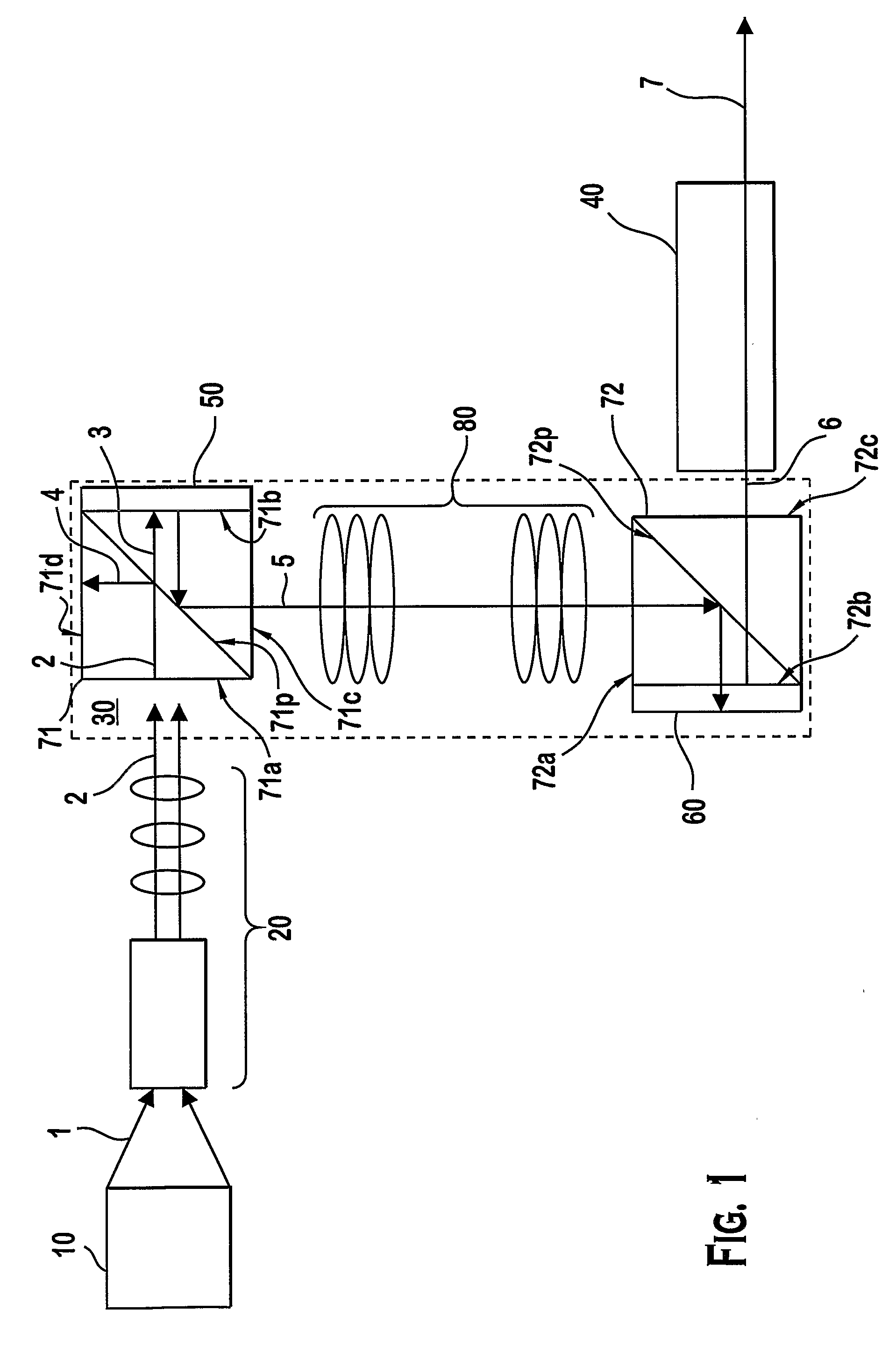
[0015] The present invention provides a projection system, such as for a television display, with enhanced contrast ratio and reduced contouring, while providing good lamp life. This is accomplished by using a larger imager 50 for the first stage to maintain a larger lamp 10, and a smaller image 60 for the second stage. In the embodiment illustrated, lamp 10 may be an arc lamp generating white light 1, suitable for use in an LCOS system. For example a short-arc mercury lamp may be used. The white light 1 enters an integrator 20, which directs a telecentric beam of white light 1 toward the projection system 30. The white light 1 is then separated into its component red, green, and blue (RGB) bands of light 2. The RGB light 2 may be separated by dichroic mirrors (not shown) and directed into separate red, green, and blue projection systems 30 for modulation. The modulated RGB light 2 is then recombined by a prism assembly (not shown) and projected by a projection lens assembly 40 onto...


PUM

PropertyMeasurementUnit
sizeaaaaaaaaaa
sizeaaaaaaaaaa
sizeaaaaaaaaaa

Abstract

A projection system is provided with improved contrast and reduced artifacts using a larger lamp to maintain good lamp life. The projection system uses two imagers, the first being larger to accommodate a large lamp, sized to the first imager and the second being smaller. The first imager has a matrix of pixels for modulating light on a pixel-by-pixel basis to form a first modulated matrix of light. The second imager has a matrix of pixels corresponding to the pixels of the first imager for modulating the first modulated matrix of light on a pixel-by-pixel basis to form a second modulated matrix of light. The second imager having a size smaller than the size of the first imager. A relay lens set provides a magnification of less than 1.0 to relay each pixel of light in the first modulated matrix of light onto a corresponding pixel of the second imager.

Description

FIELD OF THE INVENTION [0001] The invention relates to a multiple imager projection system using a large arc lamp with a projection system having a smaller imager. BACKGROUND OF THE INVENTION [0002] Microdisplays using Digital Light Processing (DLP) and / or Liquid crystal display (LCD), and particularly liquid crystal on silicon (LCOS), imagers are becoming increasingly prevalent in imaging devices such as rear projection television (RPTV). [0003] Digital Light Processing (DLP) imagers use an array of micro-mirrors, each acting as a pixel, which are pivoted at a very high rate of speed to temporally modulate light intensity on a pixel-by-pixel basis. [0004] Liquid crystal displays (LCD's), and particularly liquid crystal on silicon (LCOS) systems use a reflective light engine or imager. In an LCOS system, projected light is polarized by a polarizing beam splitter (PBS) and directed onto a LCOS imager or light engine comprising a matrix or array of pixels. Throughout this specificatio...

Claims


Application Information

Patent Timeline
Patent Type & Authority Applications(United States)
IPC IPC(8): H04N9/31G02F1/1347H04N5/74
CPCG02F1/1347H04N5/7416H04N9/3197H04N9/3126H04N5/7441G02B3/0043G02B3/02G02B9/62G03B21/28H04N9/3129
Inventor HALL, ESTILL THONE JR.
Owner THOMSON LICENSING SA
Why Eureka
Try Eureka