Plasma display device

a technology of display device and plasma, which is applied in the direction of casing/cabinet/drawer details, casing/cabinet/drawer of electric apparatus, instruments, etc., can solve the problems of easy deterioration and change, glass substrate breakage, and shorten the life of glass substrates, so as to improve heat sink efficiency and reduce manufacturing costs. , the effect of excellent thermal conductivity

Inactive Publication Date: 2007-10-04
SAMSUNG SDI CO LTD
View PDF11 Cites 25 Cited by
  • Summary
  • Abstract
  • Description
  • Claims
  • Application Information

AI Technical Summary

Benefits of technology

[0014]Accordingly, an object of the present invention is to provide a plasma display that has improved heat sink efficiency and reduced manufacturing cost by including a heat sink made of inexpensive graphite material having excellent thermal conductivity instead of an aluminum protective plate or a heat sink plate, for a TCP, or an IPM, etc., each of which produces a considerable amount of heat.

Problems solved by technology

The material of phosphors for forming the PDP have a disadvantage in that they are easily deteriorated and changed at high temperature, and their life shortened.
By overheating, especially partial overheating in the PDP, a glass substrate can break due to stress caused by thermal expansion thereof.
The drivers, which are connected to the electrodes of the PDP, also dissipate a considerable amount of power in order to display a screen.
The power dissipation results in thermal production.
As a result, if the drivers are overheated, they can cause faulty operation.
This faulty operation can cause deterioration in the quality of the screen.
Since a considerable amount of heat is produced from a driving chip of the TCP, it is difficult to cool the driving chip if it does not contact a separate heat sink.
Accordingly, a cooling problem of the driving chip occurs.
As a result thereof, the IPM produces a considerable amount of heat, and thus its cooling problem occurs.
A protection plate made of aluminum has a disadvantage in that it is expensive and thus a manufacturing cost thereof is increased.
Therefore, the protection plate made of aluminum has a disadvantage in that it is expensive and thus the manufacturing cost thereof is increased.

Method used


Image

  • Plasma display device
  • Plasma display device
  • Plasma display device

Examples


Embodiment Construction

[0035]Hereinafter, exemplary embodiments of the present invention are described in detail with reference to the accompanying drawing. The aspects and features of the present invention and methods for achieving the aspects and features will be apparent by referring to the embodiments described in detail with reference to the accompanying drawings. However, the present invention is not limited to the embodiments disclosed hereinafter, but can be implemented in diverse forms. The matters defined in the description, such as the detailed construction and elements, are merely specific details provided to assist those of ordinary skill in the art in a comprehensive understanding of the present invention, and the present invention is only defined within the scope of the appended claims. In the entire description of the present invention, the same drawing reference numerals are used for the same elements across various figures.

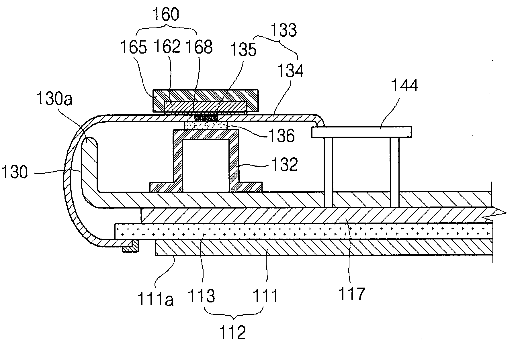
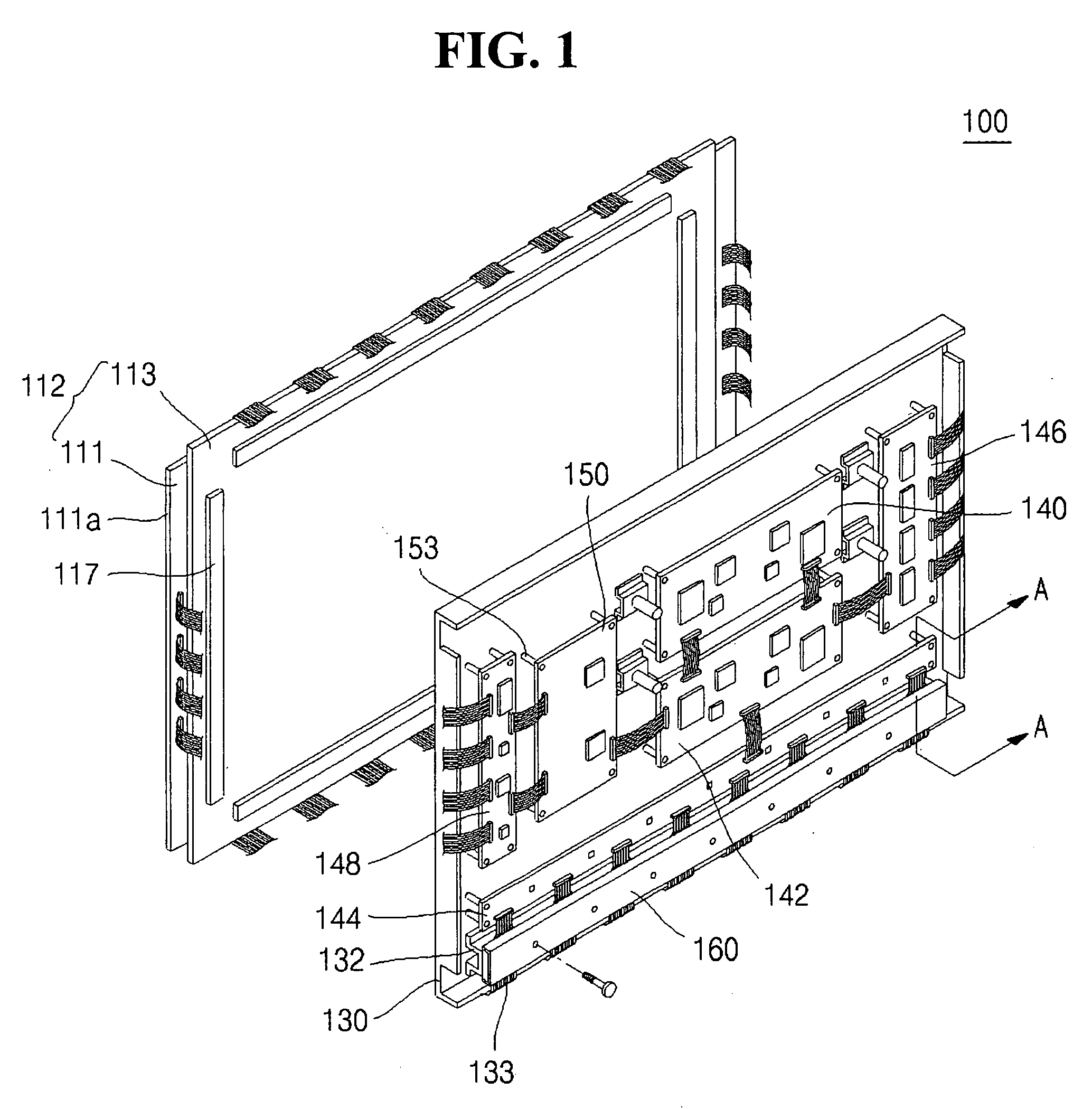
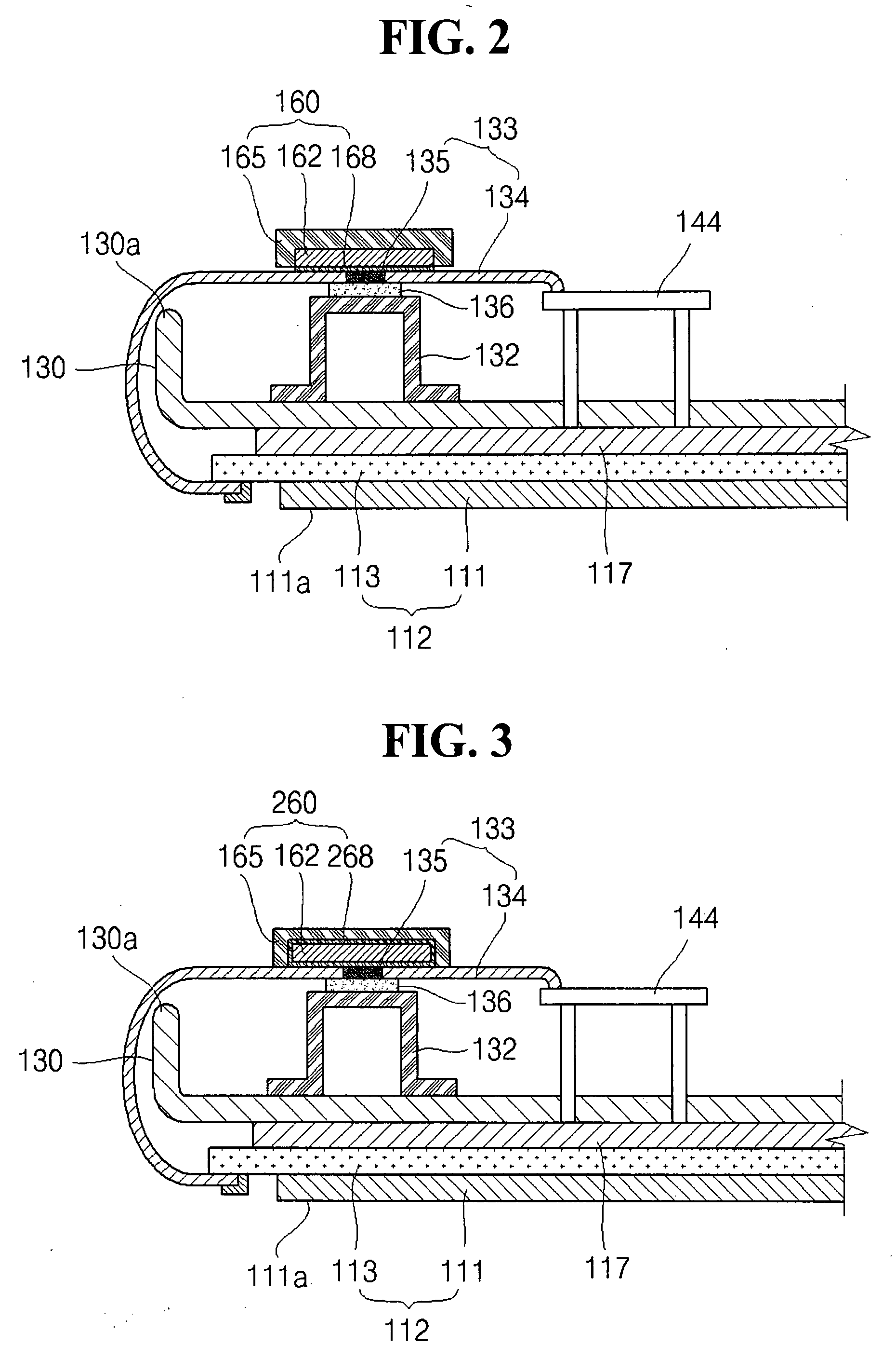
[0036]FIG. 1 is a perspective view of a plasma display according ...


PUM


Abstract

A plasma display having improved heat sink efficiency and reduced manufacturing cost includes a heat sink member made of an inexpensive graphite material having excellent thermal conductivity instead of a more expensive aluminum protective plate or a heat sink plate. The heat sink member serves as a heat sink of a Tape Carrier Package (TCP), an Intelligent Power Module (IPM), and other elements producing considerable amounts of heat.

Description

CLAIM OF PRIORITY[0001]This application makes reference to, incorporates the same herein, and claims all benefits accruing under 35 U.S.C. §119 from an application for PLASMA DISPLAY DEVICE earlier filed in the Korean Intellectual Property Office on the 29 Mar. 2006 and there duly assigned Serial No. 10-2006-0028656.BACKGROUND OF THE INVENTION[0002]1. Field of the Invention[0003]The present invention relates to a plasma display, and more particularly, the present invention relates to a plasma display having improved heat sink efficiency and reduced manufacturing cost by including a heat sink for a Tape Carrier Package (TCP), or an Intelligent Power Module (IPM), etc., the heat sink being made of inexpensive graphite material having excellent thermal conductivity instead of an aluminum protective plate or a heat sink plate.[0004]2. Description of the Related Art[0005]A plasma display is a flat panel type display using a Plasma Display Panel (PDP). The PDP is produced by forming a plu...

Claims


Application Information

Patent Timeline
Patent Type & Authority Applications(United States)
IPC IPC(8): H05K7/20
CPCH05K7/20963Y10T428/14Y10T428/30A01G3/02B26B13/04
Inventor LEE, YUJU
Owner SAMSUNG SDI CO LTD
Why Eureka
Try Eureka