
Organic electroluminescent light-emitting apparatus

a light-emitting apparatus and electroluminescent technology, applied in lighting and heating apparatus, discharge tube luminescnet screens, instruments, etc., can solve the problem that documents do not sufficiently study the application of prism members, and achieve the effect of reducing the reflection of outside light, increasing light extraction efficiency, and increasing ligh

Inactive Publication Date: 2007-10-04
CANON KK
View PDF8 Cites 16 Cited by
  • Summary
  • Abstract
  • Description
  • Claims
  • Application Information

AI Technical Summary

Benefits of technology

[0010]The present invention provides an organic EL light-emitting apparatus that has efficiency of light extraction increased by the provision of a specific prism member and a circular polarizer to a self-light-emitting device, such as an organic EL device. The EL light emitting apparatus emits more light by a reduction in the reflection of outside light.
[0012]The present invention can improve efficiency of extracted light by the provision of the prism member and the circular polarizer to the self-light-emitting device (e.g., organic EL device) and can reduce reflection of outside light.

Problems solved by technology

However, the above patent documents do not sufficiently study an application of a prism member to a light emitting apparatus that projects less glare of outside light.
However, the prism member affects the reflection of outside light and that property must be taken into account when reduction of glare is desired.

Method used


Image

  • Organic electroluminescent light-emitting apparatus
  • Organic electroluminescent light-emitting apparatus
  • Organic electroluminescent light-emitting apparatus

Examples


example 1 (

About Efficiency of Light Extraction)

[0086]An organic EL light-emitting apparatus that included a prism member was produced by the following steps.

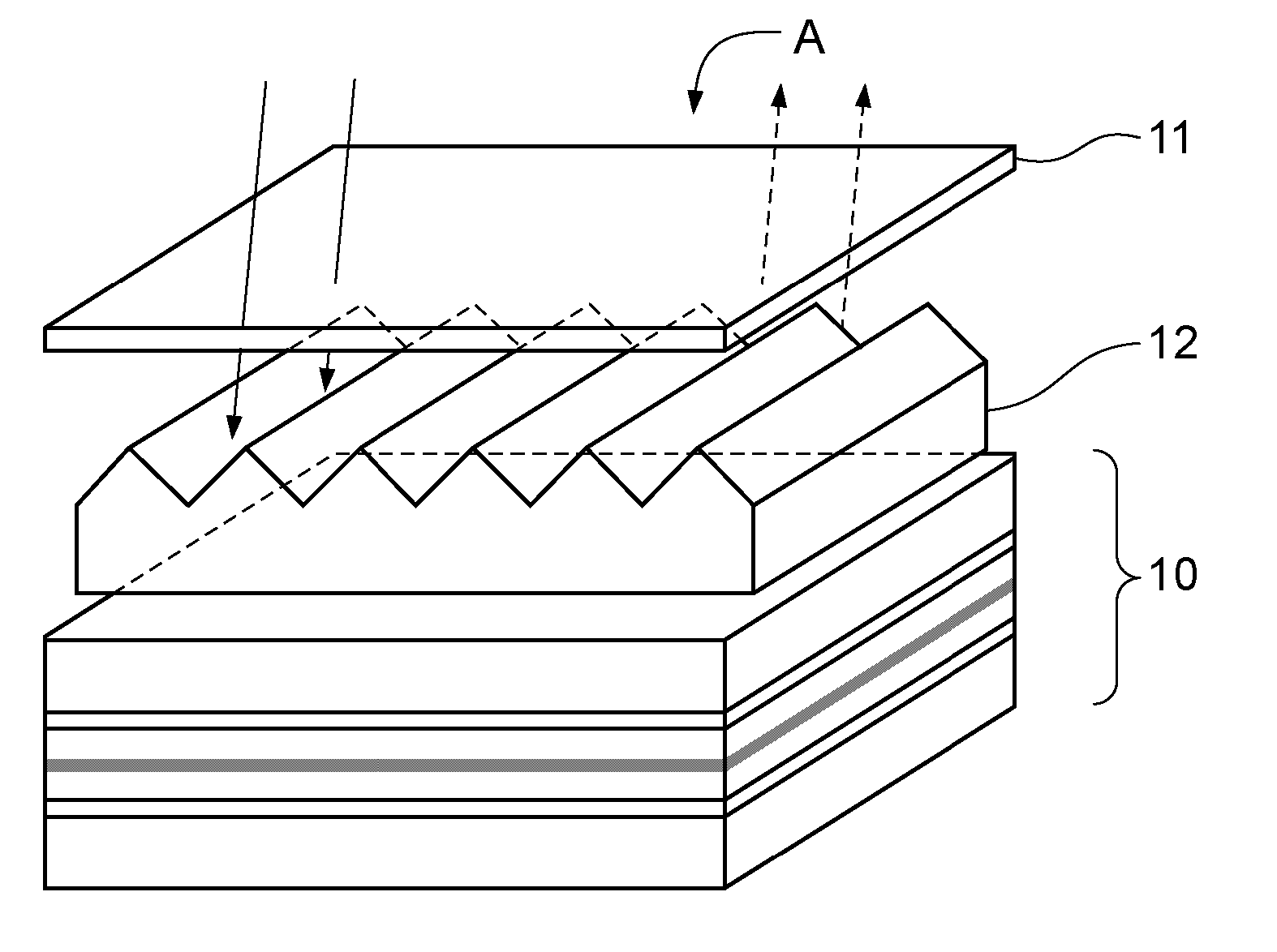
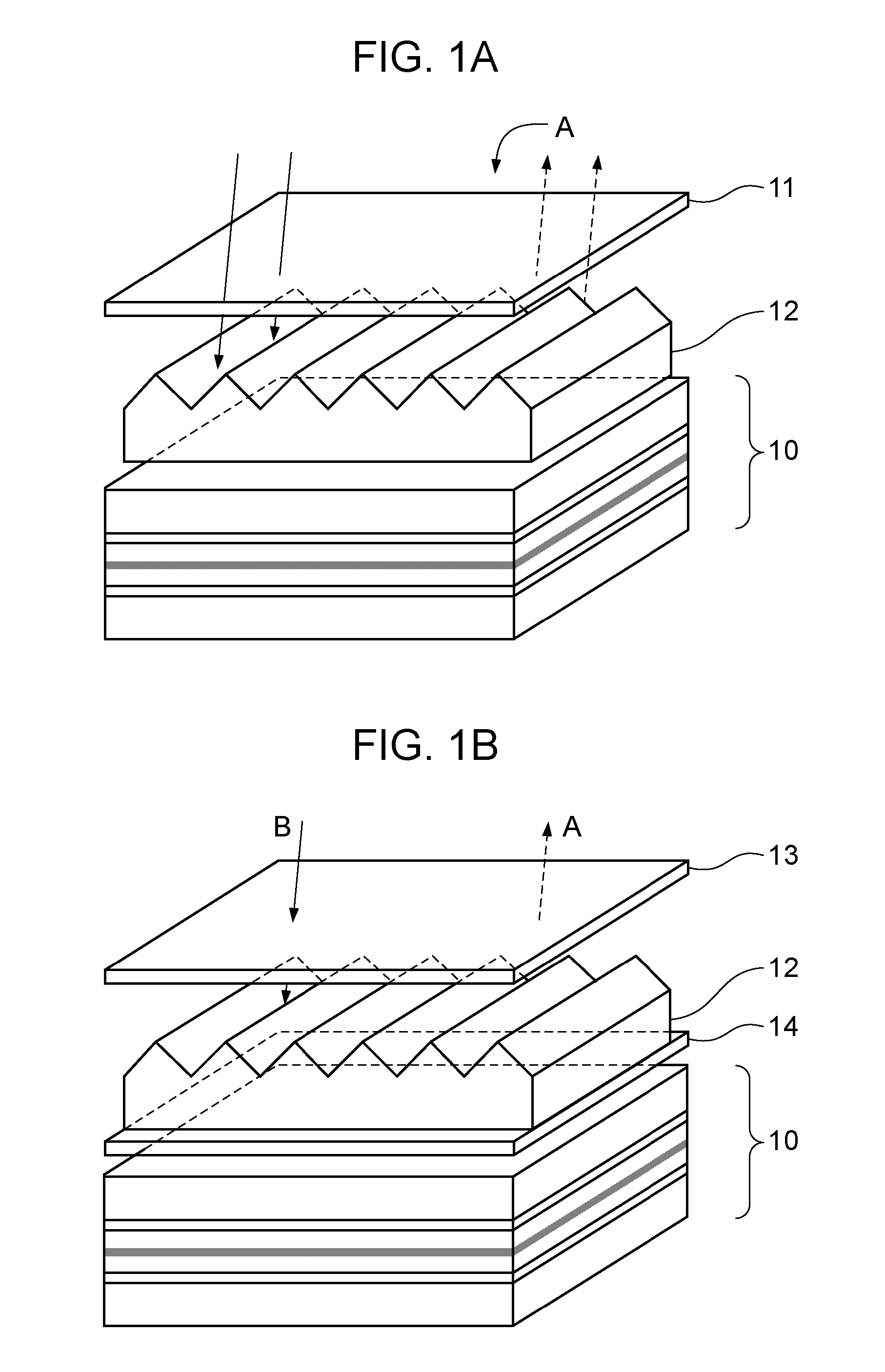
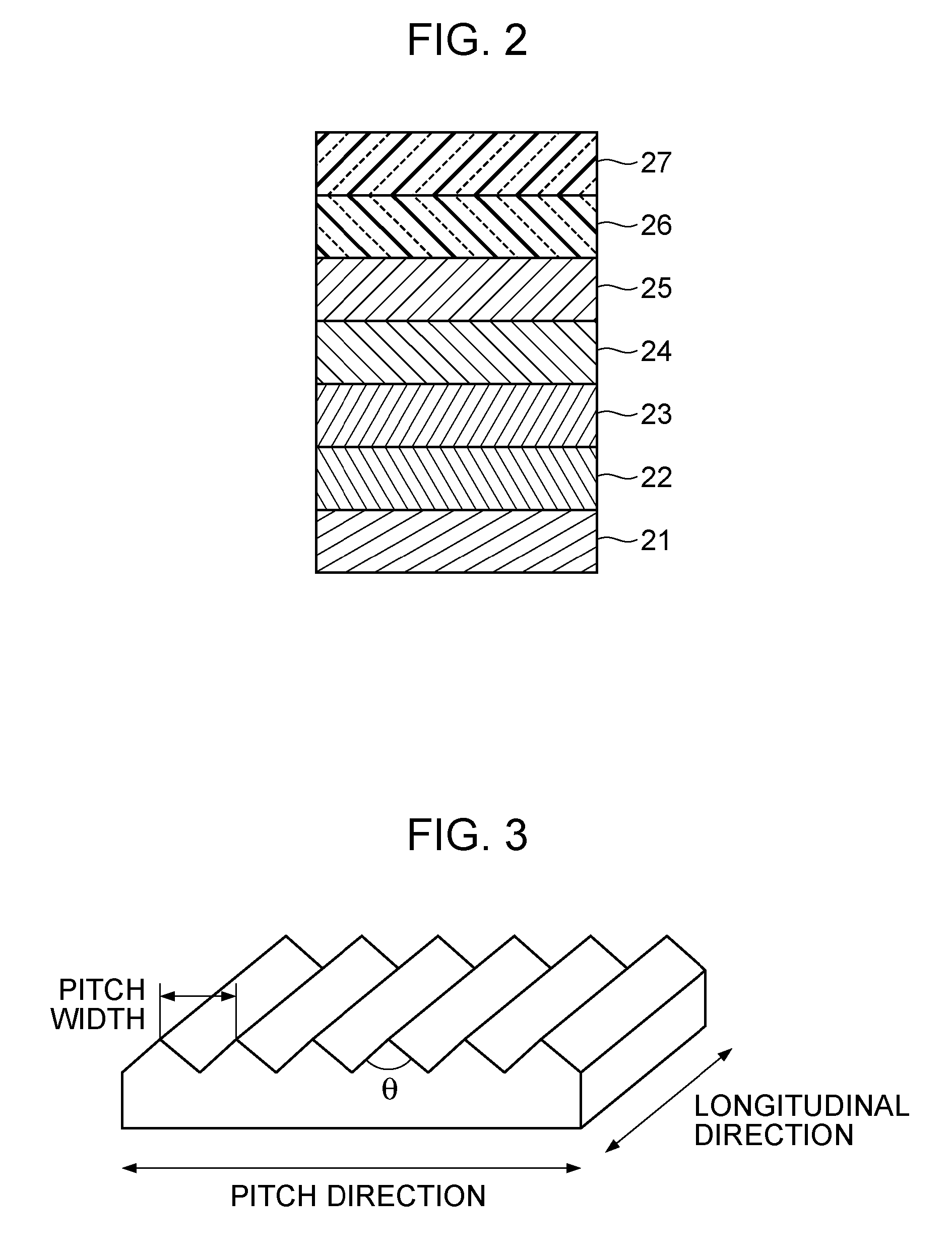
[0087]First, a device illustrated in FIG. 1A was produced. A pattern of triangular column prisms each having an apex angle of 110° at a pitch of 15 μm was formed on an optically isotropic film (sheet of a thickness of 70 μm) by being transferred by ultraviolet curing of an acrylic photocurable resin. This corresponds to the prism member. Additionally, a circular polarizer (a sheet of RD-HL56-W03 from Sanritz Corporation, having a thickness of 100 μm) was provided.

[0088]The production of the apparatus according to the exemplary embodiment is completed by laminating an organic EL device, the above prism member, and the circular polarizer together. This is referred to as a laminated member 1.

[0089]Then, a device illustrated in FIG. 1B was produced. A pattern of triangular column prisms each having an apex angle of 110° at a pitch of 15 μm wa...

example 2 (

about Antireflection for Outside Light)

[0098]To evaluate influence of reflection of outside light, a glass substrate with aluminum evaporated thereon was provided. Prism members having different apex angles were bonded to the respective substrates with an acrylic resin. Each of the bonded composites was overlaid with a circular polarizer. The influence of reflection of outside light on these samples were observed and evaluated by use of Gonio-Spectrophotometric Color Measurement System GCMS-11 from Murakami Color Research Laboratory Co., Ltd. More specifically, each sample was irradiated with substantially parallel rays of light from a standard white-light source (xenon lamp) while the incident angle was varied, and the surface of each sample was observed.

[0099]Table 4 shows the result of this experiment. When the surface looked black seen from the front and slanting directions (antireflection for outside light was effective), the evaluation is ◯. Unfortunately, when the surface loo...


PUM


Abstract

An organic EL light-emitting apparatus includes a base, an organic EL device, a prism member, a polarizing member, and a phase member. The prism member, the polarizing member, and the phase member are adjacent to a light extraction side of the organic EL device. The prism member includes a plurality of unit prisms each having a triangular-column shape. The unit prisms are arranged such that their longitudinal directions are parallel to one another. The polarizing member is disposed further from the base than the prism member. The prism member has an apex angle between 90° to 140°.

Description

BACKGROUND OF THE INVENTION[0001]1. Field of the Invention[0002]The present invention relates to an organic electroluminescent (EL) light-emitting apparatus including a prism member, a polarizing member, and a phase member disposed at a light extraction side.[0003]2. Description of the Related Art[0004]In a self-light-emitting device (e.g., an organic EL device), light incident at an angle larger than a critical angle on an interface having a larger index difference, such as that between a substrate of the device and air, is totally reflected. Therefore, actually only approximately 20% of the total amount of emitted light can be extracted to the outside. To address this problem, a technique to increase the efficiency of light extraction by providing projections and depressions to a light-extraction surface of the device is proposed.[0005]One technique to increase brightness in a known display apparatus is described in Japanese Patent Laid-Open No. 4-67016 and No. 6-308485. The techn...

Claims


Application Information

Patent Timeline
IPC IPC(8): F21V9/16
CPCF21V5/02G02B6/0053G02F2001/133607G02F1/133606G02F1/133603G02F1/133607
Inventor KITAYAMA, HIROYUKIOSATO, YOICHI
Owner CANON KK
Learn More