Preswirl guide device

Inactive Publication Date: 2007-10-04
ABB TURBO SYST
View PDF9 Cites 21 Cited by
  • Summary
  • Abstract
  • Description
  • Claims
  • Application Information

AI Technical Summary

Benefits of technology

[0006]A preswirl guide device is disclosed which can function reliably for

Problems solved by technology

In modern internal combustion engines, the adaptation of the exhaust gas turbocharger to variable operating conditions is becoming more

Method used


Image

  • Preswirl guide device
  • Preswirl guide device
  • Preswirl guide device

Examples


Embodiment Construction

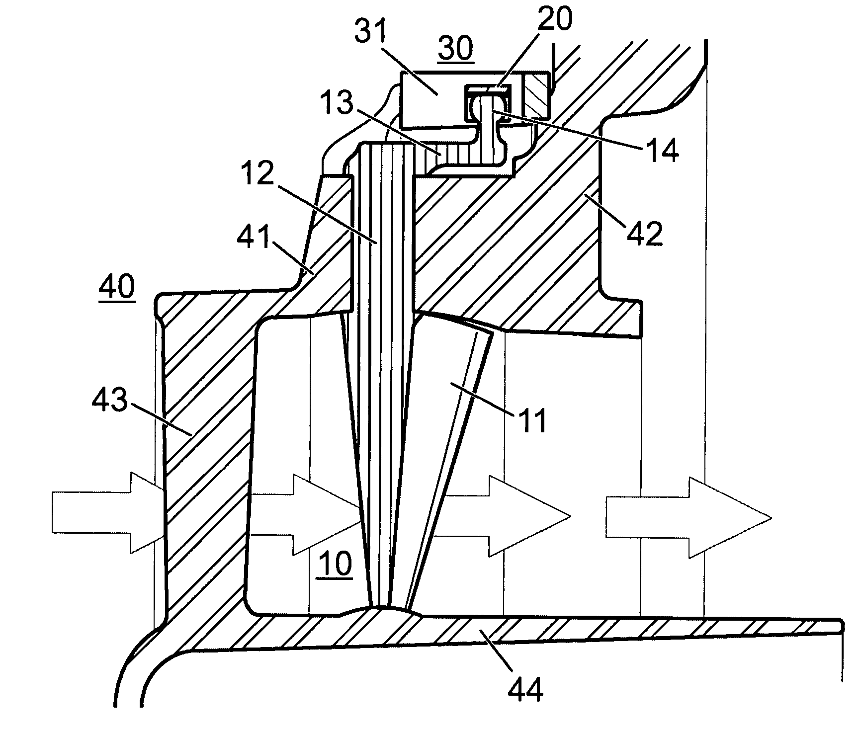
[0023]FIG. 1 shows a section through a guide device in the intake region of a compressor. As described at the beginning, such compressors are used in exhaust gas turbochargers for increasing the output of internal combustion engines. The arrows in the figure indicate the flow path of the medium to be compressed, which can be air or possibly an air / fuel mixture for the combustion process in the internal combustion engine. In addition, such guide devices can be used in any type of compressor, for example in industrial compressors driven by electric motors.

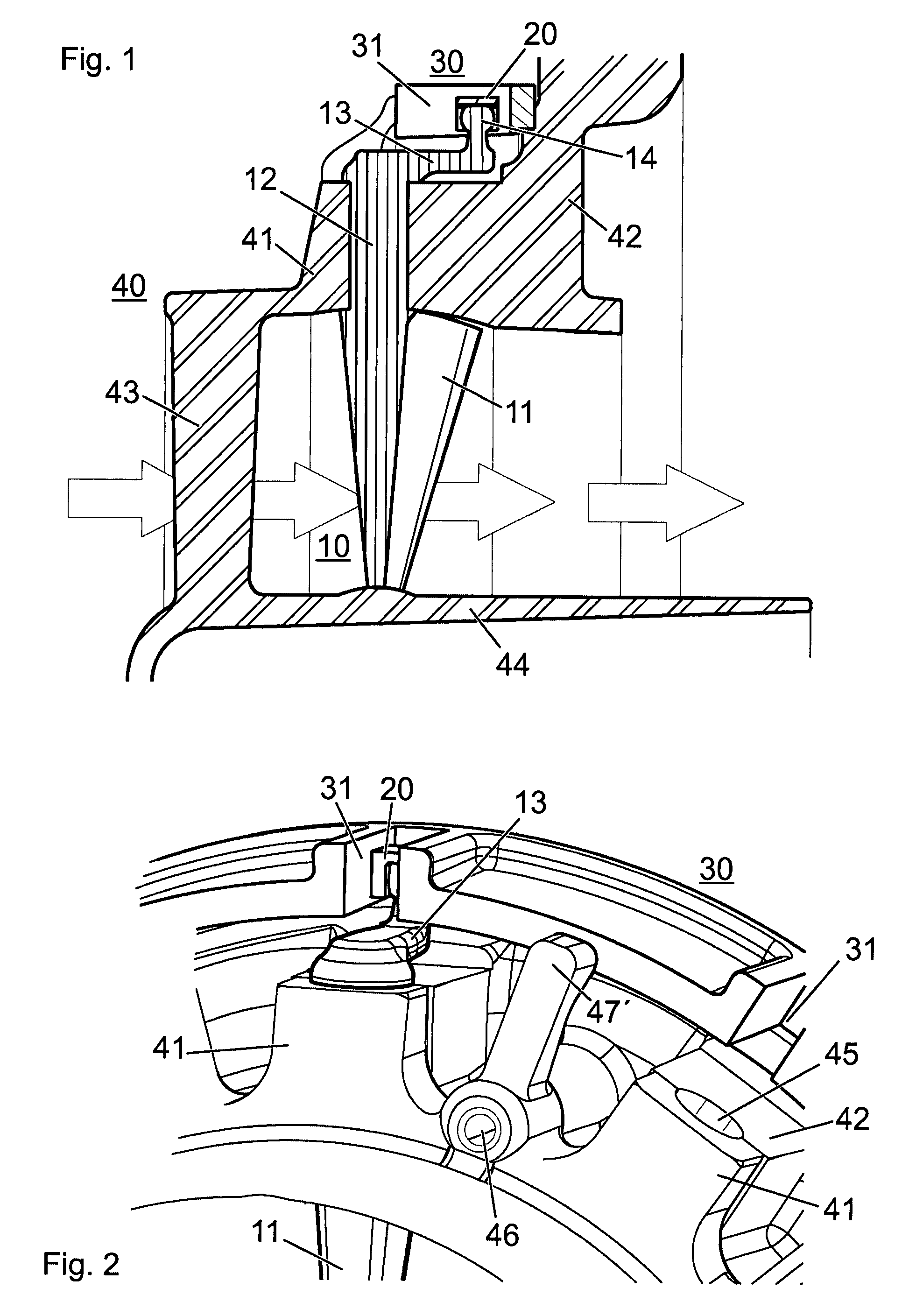
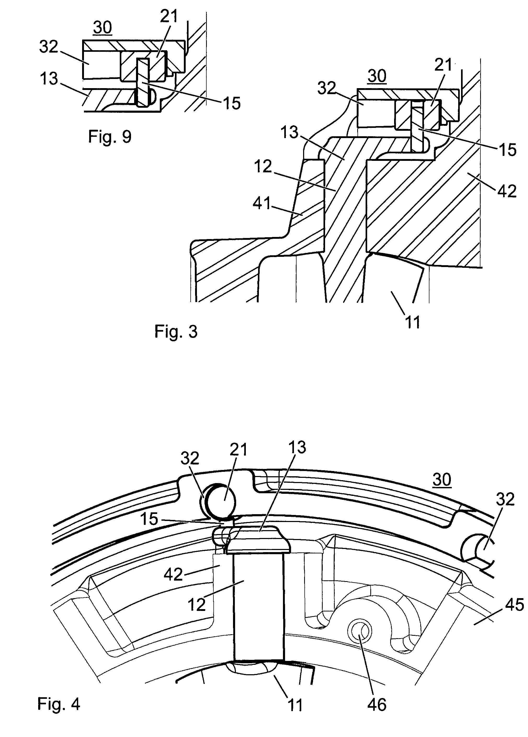
[0024]The guide device comprises a plurality of guide vanes 10 arranged so as to be oriented in the radial direction with respect to the compressor axis. Each of the guide vanes comprises, in addition to the vane profile 11 projecting into the flow duct, a vane shank 12 with which the vane profile can be rotatably mounted in a casing. The vane profile can be rotated about the axis of the vane shank via an adjusting lever 13. An adjus...


PUM


Abstract

The preswirl guide device for generating a preswirl in the intake region of a compressor comprises a multiplicity of guide vanes, which are pivotable about a respective vane shank connected to the guide vane, and a pivotable adjusting ring and adjusting levers for transmitting torque from the adjusting ring to the vane shank of each guide vane. The vane shank and the adjusting lever of the respective guide vanes are of one-piece design. The casing in which the guide vanes are rotatably mounted consists of at least two parts joined together in the region of the bearings of the guide vanes. Due to the one-piece design of the guide vane, the number of components to be fitted is reduced. This simplifies the fitting and possible service work on the guide device.

Description

RELATED APPLICATIONS[0001]This application claims priority under 35 U.S.C. §119 to EP Application 06405137.8 filed in Europe on Mar. 31, 2006, the entire contents of which are hereby incorporated by reference in their entireties.TECHNICAL FIELD[0002]The disclosure relates to the field of turbomachines to which exhaust gases of internal combustion engines are admitted. A guide device is disclosed for generating a preswirl in the intake region of a compressor and an exhaust gas turbocharger having such a preswirl guide device.BACKGROUND INFORMATION[0003]Exhaust gas turbochargers are used for increasing the output of internal combustion engines. In modern internal combustion engines, the adaptation of the exhaust gas turbocharger to variable operating conditions is becoming more and more difficult. What is referred to as the variable turbine and / or compressor geometry offers a widespread possibility in this respect. In the variable turbine geometry, the guide vanes of the distributor u...

Claims


Application Information

Patent Timeline
IPC IPC(8): F04D29/56
CPCF04D29/462F04D29/4213F05D2250/51F01D17/16F04D29/46
Inventor OESCHGER, DANIELBATTIG, JOSEFKOPP, ADRIANKUHNEL, JANPETER
Owner ABB TURBO SYST
Why Eureka
Try Eureka