Dynamic compensation system for maskless lithography

a dynamic compensation and maskless technology, applied in the field of printing patterns, can solve the problems of time elapse during the patterning process, face challenges involving time and space, and remain to be addressed, and achieve the effect of improving the registration of one layer of patterning to a subsequent layer of patterning, and high speed

Inactive Publication Date: 2007-10-04
EASTMAN KODAK CO
View PDF4 Cites 19 Cited by
  • Summary
  • Abstract
  • Description
  • Claims
  • Application Information

AI Technical Summary

Benefits of technology

[0010] According to the invention, corrections of the location of the written spot are altered in both X and Y dimensions across the substrate image plane, resulting in improvements in the registration of one layer of patterning to a subsequent layer of patterning.
[0011] According to a further aspect of the invention, the system utilizes information about the prior patterning layers to enable precision detection at high speed of the relative location of the printhead and the substrate pattern.

Problems solved by technology

There are, however, challenges that remain to be addressed to truly enable the process of maskless lithography on large substrates.
As this shift occurs, then one is faced with challenges involving time and space.
First, time will elapse during the patterning process.

Method used


Image

  • Dynamic compensation system for maskless lithography
  • Dynamic compensation system for maskless lithography
  • Dynamic compensation system for maskless lithography

Examples


Embodiment Construction

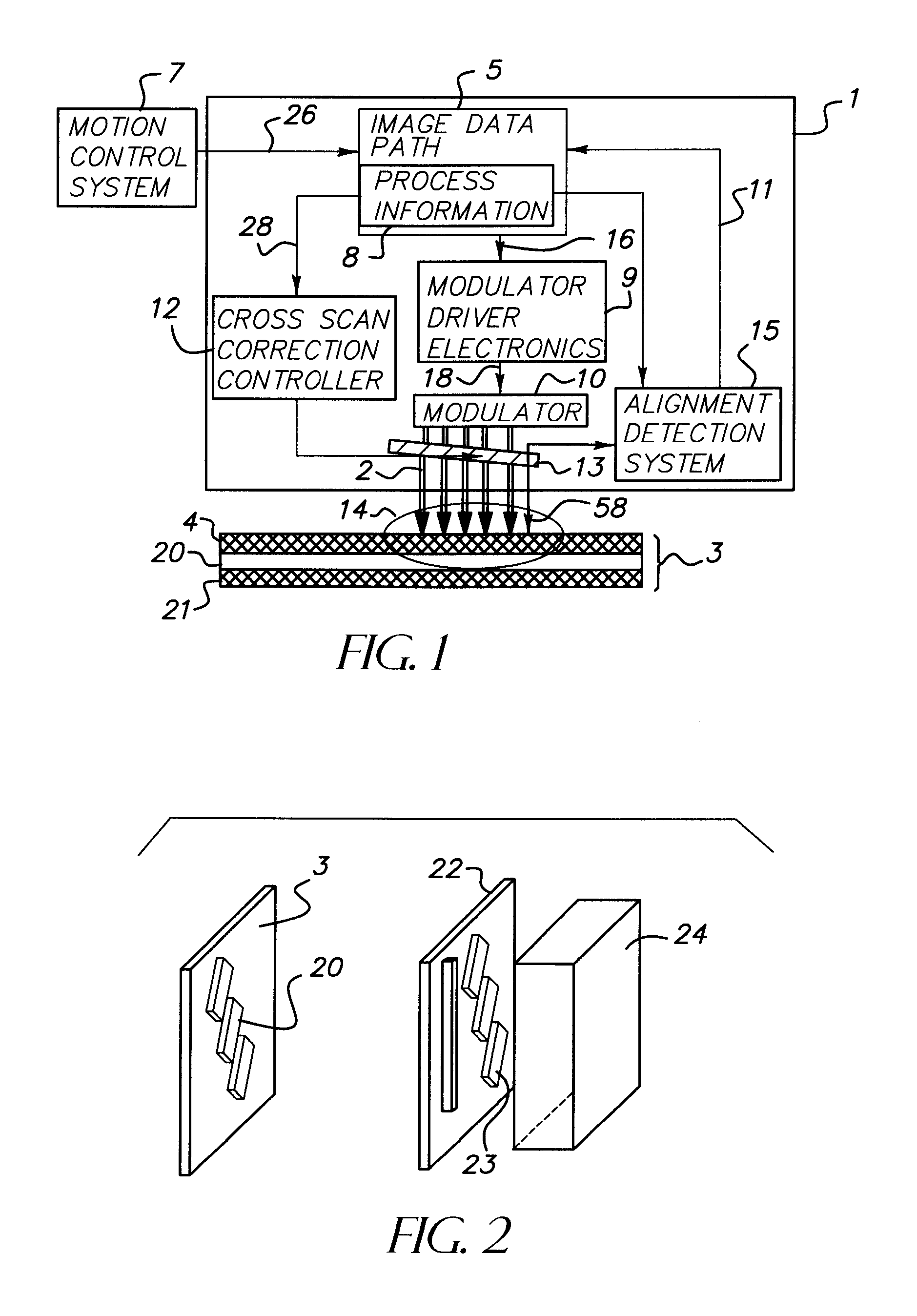
[0033] The present invention is closed loop control system, which acts to align a second pattern that is being generated with a first pattern. The closed loop system operates dynamically, meaning that it operates during and integral with the pattern forming process. As a result, no additional alignment overhead is required.

[0034] Various pattern forming means exist that are compatible with this invention. The preferred embodiment describes a process whereby a substrate having a patterned first layer is coated with sensitive materials 4, as shown in FIG. 1. A pattern is formed in this second coated layer. One means of forming this pattern is through laser ablation. Alternately, the pattern can be formed through modification of a material coupled with a subsequent step. For example, one could sinter a material and wash off the not sintered components of the second layer. Or, one could polymerize a material and wash off the non-polymerized components of the second layer.

[0035] In add...


PUM

PropertyMeasurementUnit
channel sizeaaaaaaaaaa
wavelengthaaaaaaaaaa

Abstract

A method for dynamically registering multiple patterned layers on a substrate (3) comprises: depositing a first layer on the substrate; printing a first pattern (20) on the first layer; depositing a second layer on the first pattern; and printing a second pattern on the second layer while dynamically detecting the first pattern to align the second pattern with the first pattern.

Description

FIELD OF THE INVENTION [0001] This invention relates in general to printing patterns on a substrate and in particular, to printing multiple patterns on a substrate while dynamically aligning the patterns. BACKGROUND OF THE INVENTION [0002] Lithography was introduced to the electronics industry in the 1950's. The first integrated circuit was produced in 1960 by the firms Fairchild Semiconductor and Texas Instruments. Lithographic processes are used in both back plane and front plane display manufacturing. During the past 10 years, lithographic processes have been applied to new areas of precision patterning such as patterned synthesis of nucleic acid structures required for DNA testing. [0003] In 1990 M. Rieger et al. described the value associated with direct write lithography, or maskless lithography. It has been broadly claimed that the elimination of masks will reduce process cost, increase process yield and enable the use of larger substrates. The use of laser patterning and lig...

Claims


Application Information

Patent Timeline
Patent Type & Authority Applications(United States)
IPC IPC(8): G03F9/00G03C5/00
CPCG03F7/70291G03F9/7003G03F7/70791G03F7/70633G03F7/70466G03F7/70516
Inventor RIVERS, ANDREA S.TREDWELL, TIMOTHY J.CUFFNEY, ROBERT H.STOOPS, JAMES T.COBB, JOSHUA M.
Owner EASTMAN KODAK CO
Why Eureka
Try Eureka