

MRI biopsy device
a biopsy device and tissue technology, applied in medical science, surgery, vaccination/ovulation diagnostics, etc., can solve the problems of limiting the number of such apertures, the corresponding number of access points available to the clinician, and the less effective compression member in securing the breast,
- Summary
- Abstract
- Description
- Claims
- Application Information
AI Technical Summary
Problems solved by technology
Method used
Image

Examples
Embodiment Construction
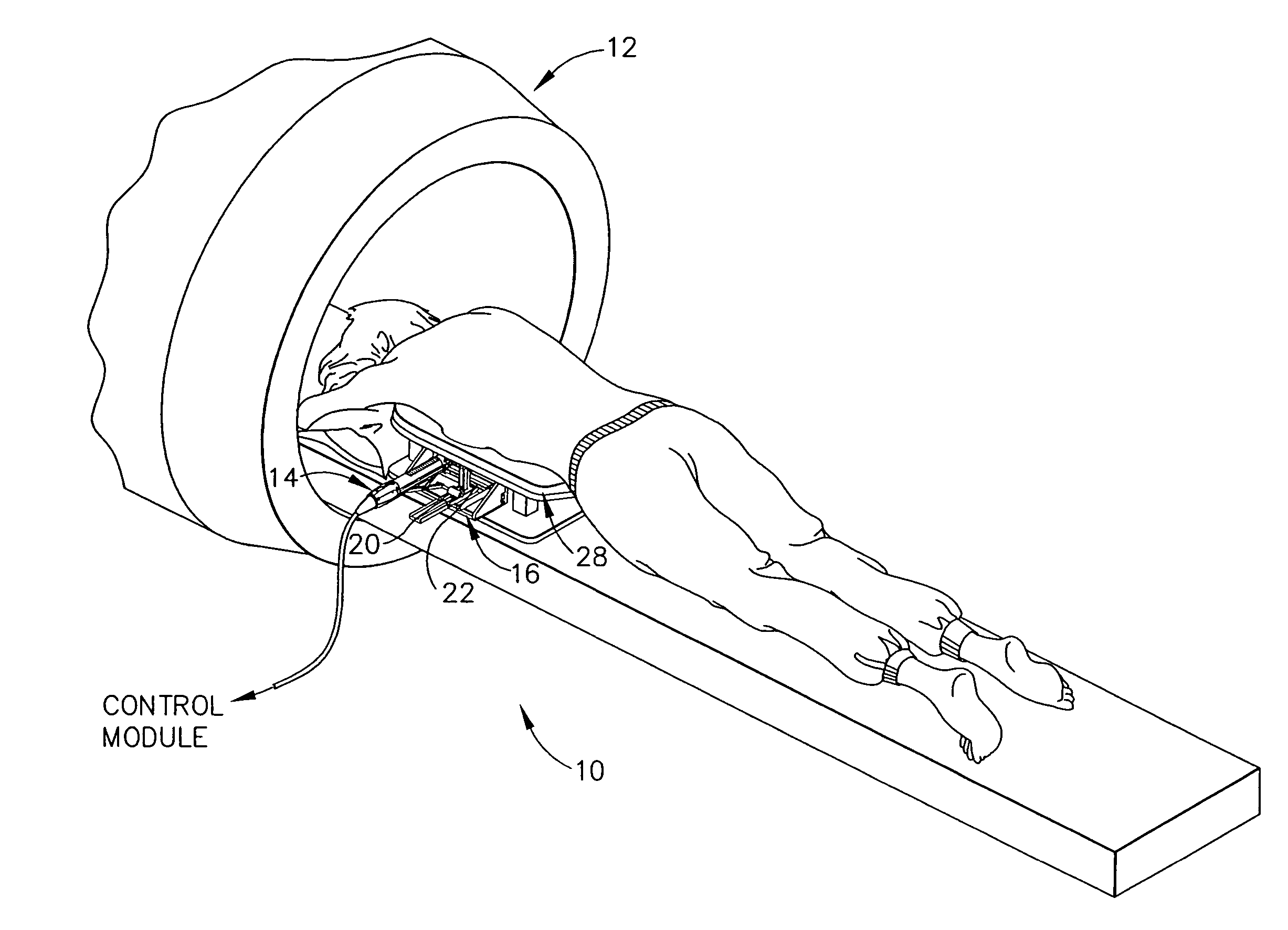
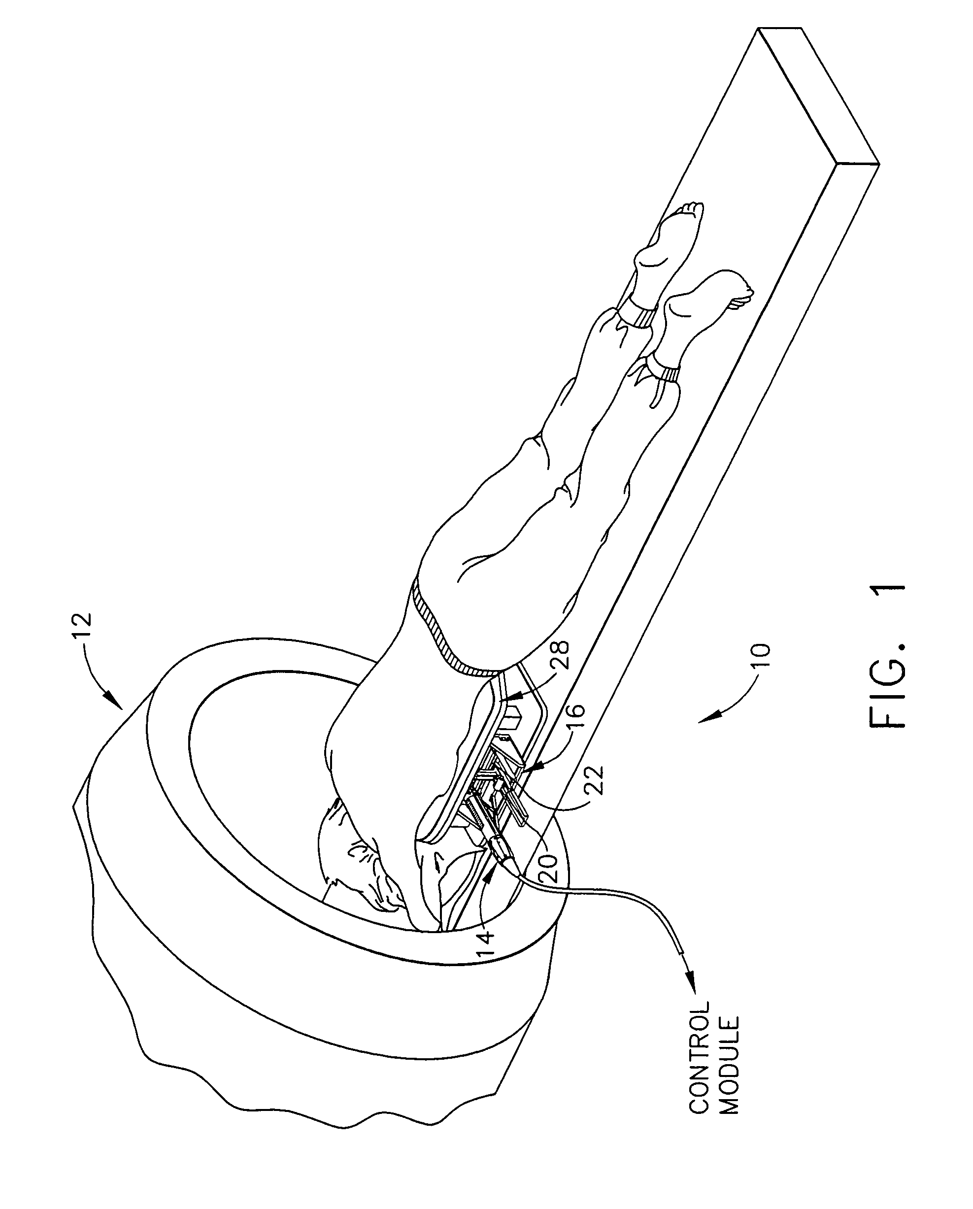
[0040] Turning to the Drawings, wherein like numerals denote like components throughout the several views, in FIG. 1, a Magnetic Resonance Imaging (MRI) biopsy system 10, hereinafter biopsy system 10, includes an MRI machine 12, a patient support 28, a localization fixture 16, and a biopsy device 14.
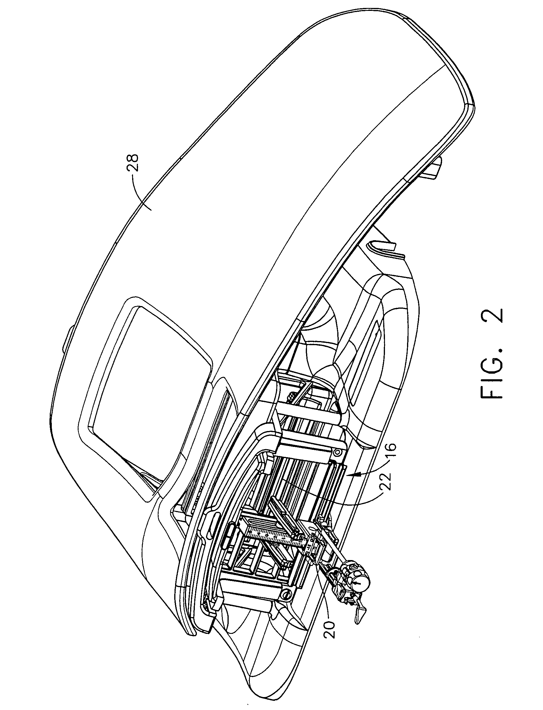
[0041] Referring to FIGS. 1-3, the biopsy system 10 includes a control module (not shown) that typically is placed outside of a shielded room containing an MRI machine 12, or at least spaced away, to mitigate detrimental interaction with its strong magnetic field and / or sensitive radio frequency (RF) signal detection antennas. The control module controls and powers the biopsy device 14, which is compatible for use in close proximity to the MRI machine 12. An example of a biopsy device 14 is the afore-mentioned MAMMOTOME™ instrument. The biopsy device 14 is accurately positioned by a localization fixture 16 that is attached to a patient support 28, which supports a patient throughout the...
PUM
 Abstract
Description
Claims
Application Information