System and method of redundancy management for fault effect mitigation

a technology of redundancy management and fault effect, applied in the field of electronic control system, can solve problems such as significant consequences of error or loss of function, subject to verification rigor, and add difficulty in the implementation of dissimilar redundancy

Active Publication Date: 2007-10-04
HONEYWELL INT INC
View PDF6 Cites 23 Cited by
  • Summary
  • Abstract
  • Description
  • Claims
  • Application Information

AI Technical Summary

Problems solved by technology

Each of these systems has an associated criticality and is generally subject to verification rigor based on such criticality.
One concern is with the occurrence of a generic fault, particularly for a highly critical functionality, such as FBW where the system is full-time (e.g., from “wheels-up” until “wheels-down”), in which an error or loss of function has significant consequences.
The functionalities associated with complex hardware devices, such as programmable logic devices (PLDs) and application specific integrated circuits (ASICs), add difficulty to the implementation of dissimilar redundancy and require specific architectural treatment in the design and / or application of dissimilar redundancy.
Additionally, dissimilar redundancy may be difficult to implement for complex communications paths within the FBW electronic system thereby necessitating architectural treatment to limit the potential fault effects and mitigate what would otherwise be a full-time exposure to critical fault scenarios in complex devices.

Method used


Image

  • System and method of redundancy management for fault effect mitigation
  • System and method of redundancy management for fault effect mitigation
  • System and method of redundancy management for fault effect mitigation

Examples


Embodiment Construction

[0016] The following detailed description of the invention is merely exemplary in nature and is not intended to limit the invention or the application and uses of the invention. Furthermore, there is no intention to be bound by any theory presented in the preceding background of the invention or the following detailed description of the invention.

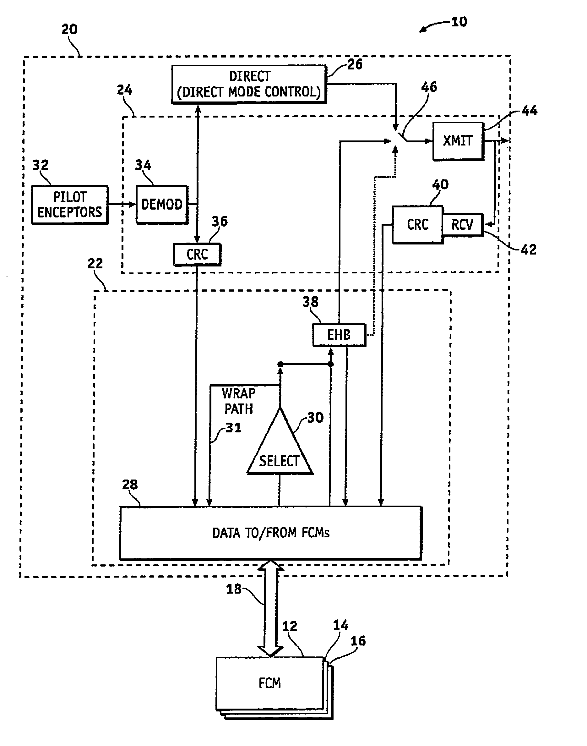
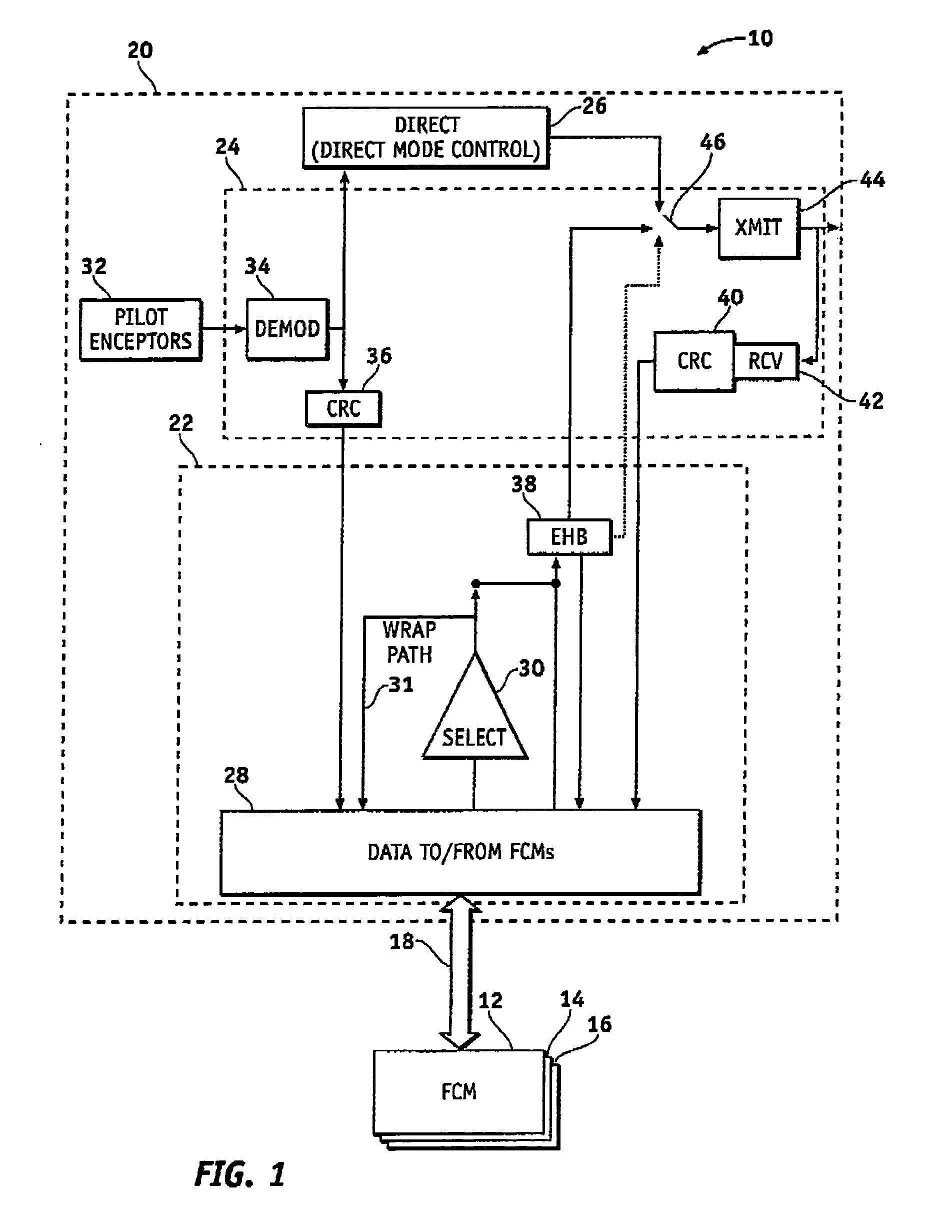
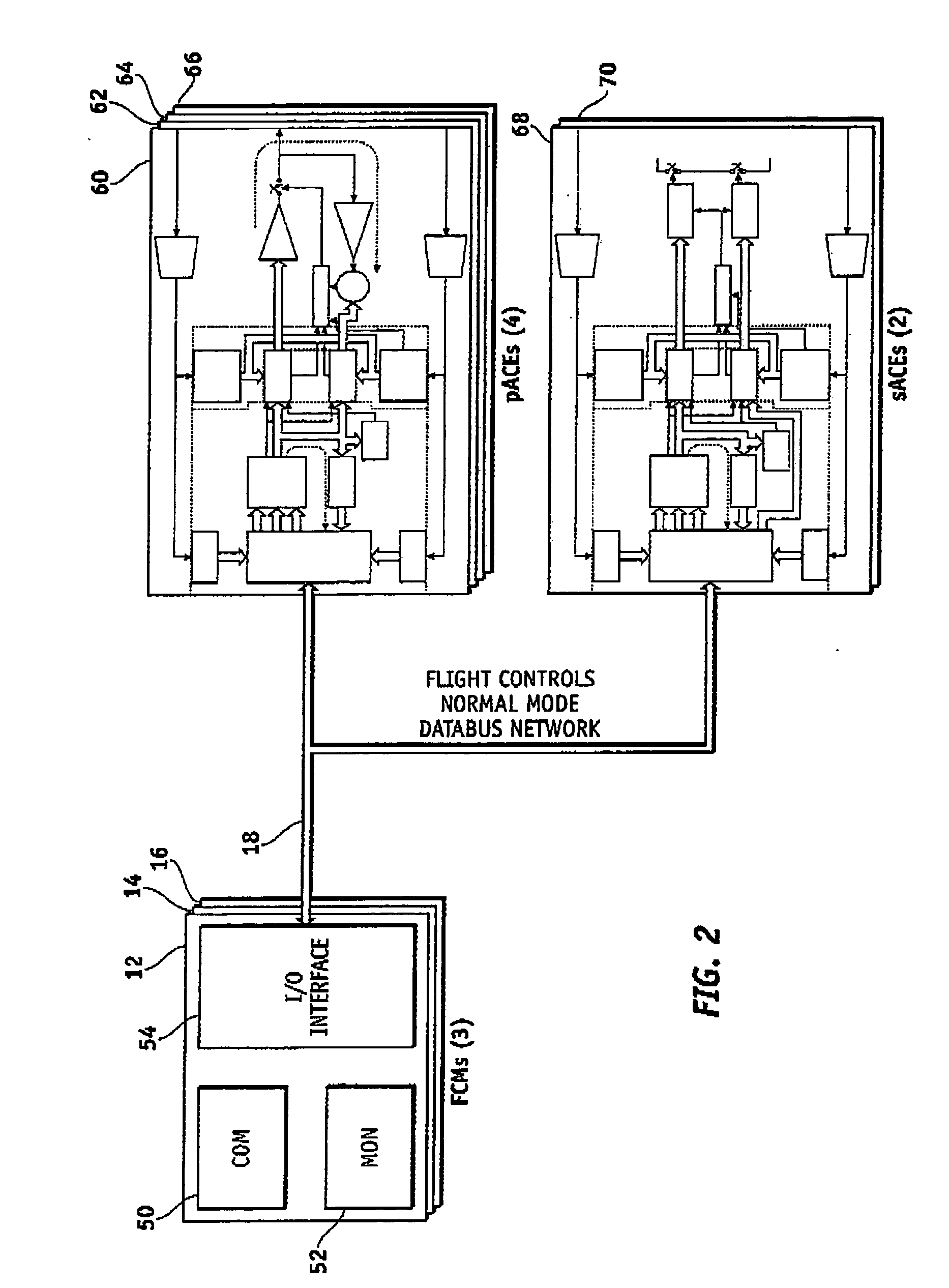
[0017] The present invention is a control system and method for architectural mitigation of failures of a normal mode partition in the control system. In one exemplary embodiment, the control system comprises the normal mode partition, a direct mode partition, and a common partition that is preferably “simple” in compliance with DO-254. Both of the normal mode partition and the direct mode partition operate with portions of the common partition to produce output command signals. The control system is configured to receive computed command signals from an external source (e.g., one or more flight control modules (FCMs)) and generate output ...


PUM


Abstract

Methods and systems are provided for redundancy management of a fly-by-wire avionics system. A control module for producing a control signal is provided comprising a common processing partition for receiving a flight input signal and at least one first mode input signal, a first processing partition coupled to the common processing partition and configured to receive the first mode input signals and flight input signal from the common processing partition, and a second processing partition coupled to the common processing partition. The first processing partition produces a first mode output signal in response to one of the first mode input signals and flight input signal. The second processing partition generates a second mode signal in response to the flight input signal when the first processing partition fails. The common processing partition produces the control signal in response to one of the first mode output signal and second mode signal.

Description

FIELD OF THE INVENTION [0001] The present invention generally relates to electronic control systems, and more particularly relates to systems and methods for redundancy management in electronic control systems such as Fly-By-Wire (FBW) avionics systems. BACKGROUND OF THE INVENTION [0002] Modern aircraft are increasingly equipped with fly-by-wire (FBW) systems that replace many mechanical flight control systems. Complex mechanical assemblies were commonly incorporated in older aircraft to transmit pilot inputs / commands to various flight control surfaces, e.g., the rudder, elevator, and ailerons, of the aircraft. FBW systems were designed to convert the pilot inputs / commands into electrical signals (e.g., via transducers) that when combined with other data control the flight control surfaces. For example, electronic sensors are attached to the pilot's controls. These sensors transmit electronic data to actuator control modules (ACEs), as an intermediate destination, and this sensor da...

Claims


Application Information

Patent Timeline
Patent Type & Authority Applications(United States)
IPC IPC(8): G01C23/00
CPCG05D1/0077
Inventor BEUTLER, ARTHUR D.YOUNT, LARRY J.BRACK, KAREN
Owner HONEYWELL INT INC
Why Eureka
Try Eureka