Energy conversion device and operation method thereof

a technology of energy conversion device and operation method, which is applied in the direction of special engines, ericsson type engines, hot gas positive displacement engine plants, etc., can solve the problems of difficult packaging, increased radiator size, and complicated dissipation of waste heat, so as to increase the efficiency of the heat machine, and increase the efficiency of the total heat machine

Inactive Publication Date: 2007-10-11
SCHUSTER ALEXANDER +1
View PDF3 Cites 12 Cited by
  • Summary
  • Abstract
  • Description
  • Claims
  • Application Information

AI Technical Summary

Benefits of technology

This patent describes a new design for heat machines which has several advantages over traditional designs. Firstly, the heat energy collected by the machine is separated from the main part of the system, making it easier to use and increase the efficiency of the machine. Secondly, the amount of heat stored inside the machine lasts longer compared to previous designs. Thirdly, the timing of different parts in the process can be controlled, allowing for optimal performance at certain times. Fourthly, the design uses a special type of heat exchanger called a counterflow heat exchanger, which has infinite heat capacity and reduces the likelihood of excessive pressure drop. Fifthly, the design also results in reduced friction and improved pneumatic performance. Finally, combining multiple heat machines into one unit creates stronger mechanical properties and simplified construction.

Problems solved by technology

The technical problem addressed in this patent is finding efficient methods for reducing the amount of energy lost to the reservoir (Qloss) in heat machines operating on a regenerative thermodynamic cycle with cyclic compression and expansion of the working fluid at different temperature levels using repeated heating and cooling of a sealed amount of working gas. The patent describes various prior art devices and methods for achieving this goal.

Method used


Image

  • Energy conversion device and operation method thereof
  • Energy conversion device and operation method thereof
  • Energy conversion device and operation method thereof

Examples


Embodiment Construction

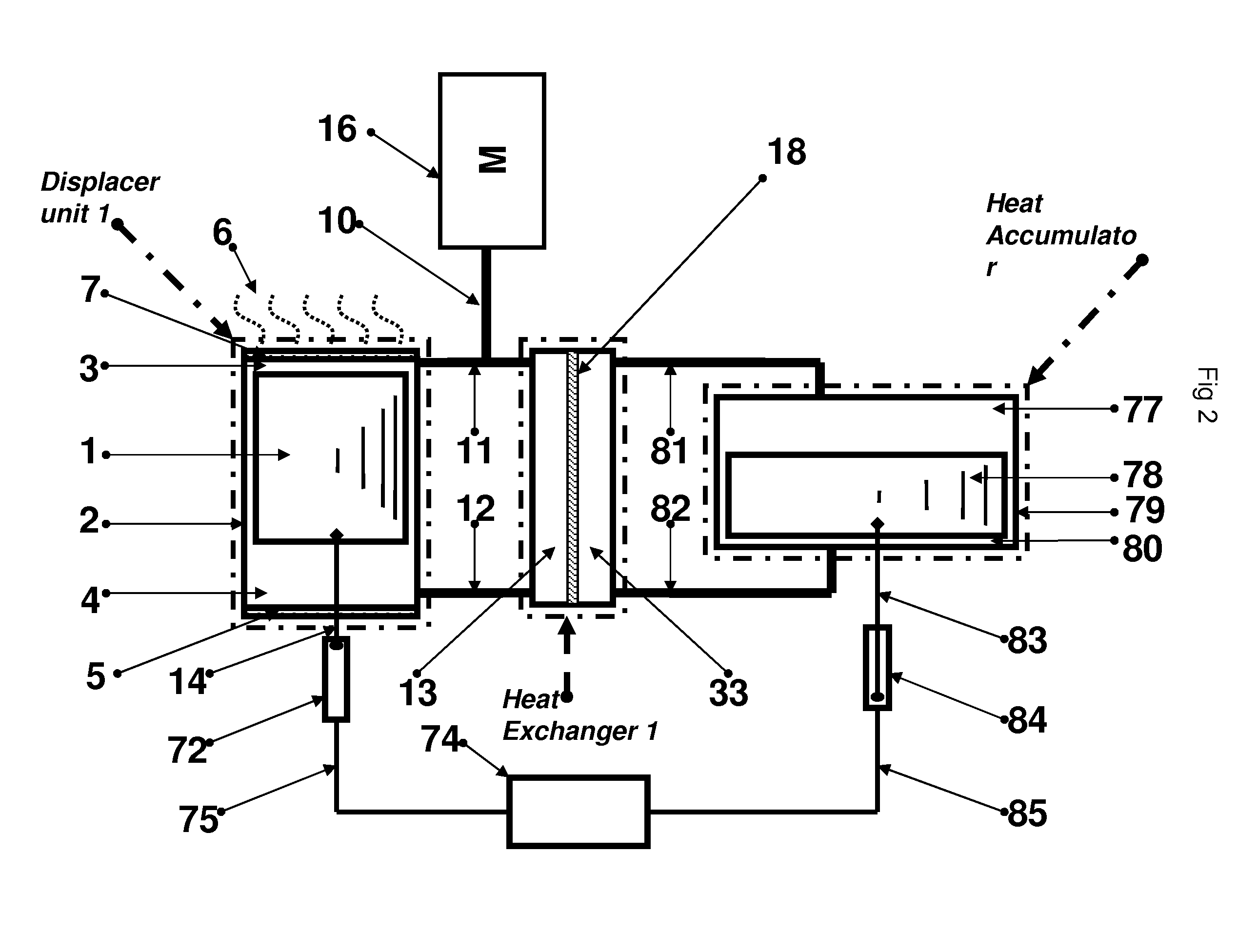
[0103] Referring first to FIG. 2, is illustrated an energy conversion device that can operate both as an engine or a heat pump according to one embodiment of this invention. The energy conversion device is comprised of two displacer units (Heat Machine 1, Heat Accumulator), a counterflow heat exchanger and a work machine (16) that is capable of receiving / transmitting variations of pressure.

[0104] Each displacer unit is comprised of a displacer chamber (2, 79), displacer (1, 78), a hot zone (3, 77), a cold zone (4, 80) and an actuating drives (14, 83) to drive the displacers by the commands of the external control unit. Displacer chamber of Heat Machine 1 further includes two heat exchangers: the first heat exchanger surface (7) which enables heat exchange of the high temperature heat energy between the heat source (6) and the hot zone (3) and a second heat exchange surface (5) which enables heat exchange of the low temperature heat energy between the cold zone (4) and the reservoir...


PUM


Abstract

The present invention suggested a new energy conversion device implementing regenerative gas cycle. The energy conversion device is comprised of: a work machine that is capable of receiving and transmitting variations of pressure, at least two displacer units each including a hot and cold zone and a displacer element for moving an actuating medium from the hot zone to the cold zone, at least one counterflow heat exchanger for enabling heat exchange between actuating mediums of displacer units, wherein the actuating medium of the displacers units flows through the counterflow heat exchanger from the hot zone to the cold zone and vice versa and a controlling device capable of controlling the movement of displacers elements, at least four conduits for connecting between the counterflow heat exchanger to the displacer units.

Description


Claims


Application Information

Patent Timeline
Owner SCHUSTER ALEXANDER
Why Eureka
Try Eureka