Method and Apparatus for Fray-Free Cutting with Laser Anti-Fray Inducement

a technology of anti-fray and laser, applied in the field of textile processing technology, can solve the problems of loss of precision cutting advantages and woven or non-woven materials, and achieve the effects of avoiding any visual impact, and minimizing the path width

Inactive Publication Date: 2007-10-11
MIKKELSEN GRAPHIC ENG
View PDF68 Cites 9 Cited by
  • Summary
  • Abstract
  • Description
  • Claims
  • Application Information

AI Technical Summary

Benefits of technology

[0009]Still another object of the invention is to provide anti-fray cutting apparatus and method which precisely creates an anti-fray condition on the sheet to achieve the desired protection.
[0014]In highly preferred embodiments, the support structure includes a support beam spanning the textile-receiving surface and reversibly movable therealong, and the anti-fray instrument is reversibly movable along the beam. In some preferred embodiments the cutter is also attached to such beam and is reversibly movable therealong. The anti-fray instrument and the cutter are preferably movable both with the beam (i.e., movement in the X-direction) and with respect to (along) the beam (i.e., movement in the Y-direction) in a manner providing independent concurrent movement thereof In certain highly preferred embodiments of this type, for perimeter lines extending parallel to the direction of beam movement the controller is further programmed for concurrent creation of the anti-fray condition in the sheet by the anti-fray instrument and cutting by the cutter with the anti-fray instrument and the cutter in the same Y-position along the beam, thereby to increase productivity.

Problems solved by technology

Many textile materials of woven or non-woven nature tend to fray when cut into pieces or shapes and subsequently handled during various operations.
Indeed, advantages of precision cutting tend to be lost due to fraying and other edge-related concerns.

Method used


Image

  • Method and Apparatus for Fray-Free Cutting with Laser Anti-Fray Inducement
  • Method and Apparatus for Fray-Free Cutting with Laser Anti-Fray Inducement
  • Method and Apparatus for Fray-Free Cutting with Laser Anti-Fray Inducement

Examples


Embodiment Construction

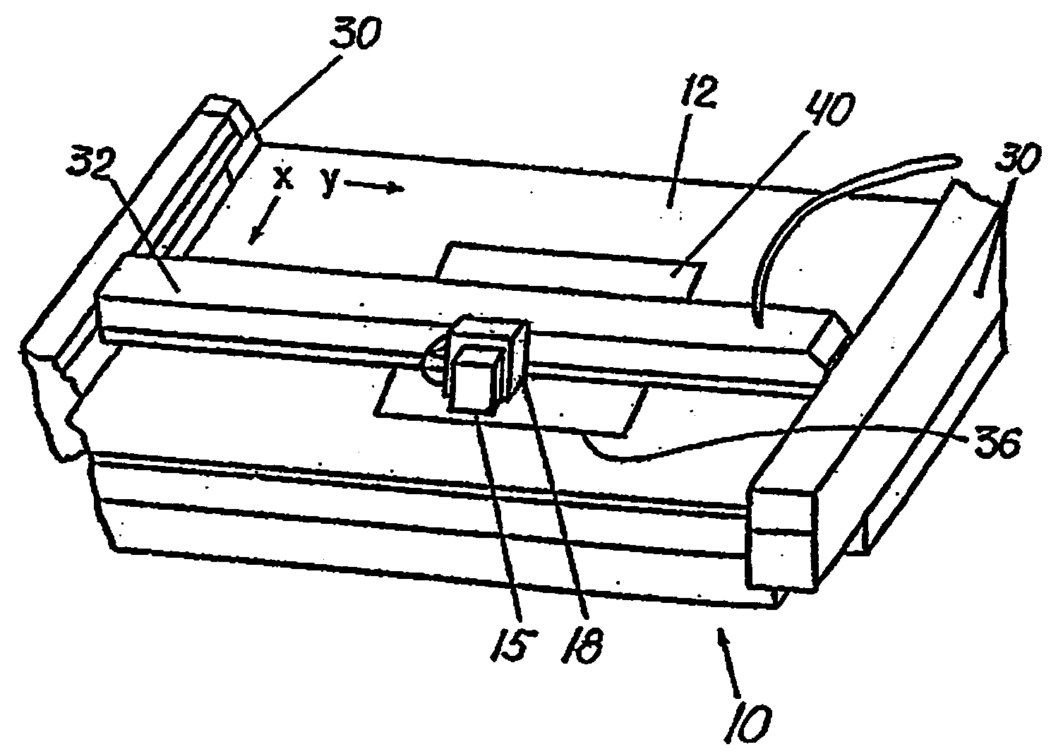
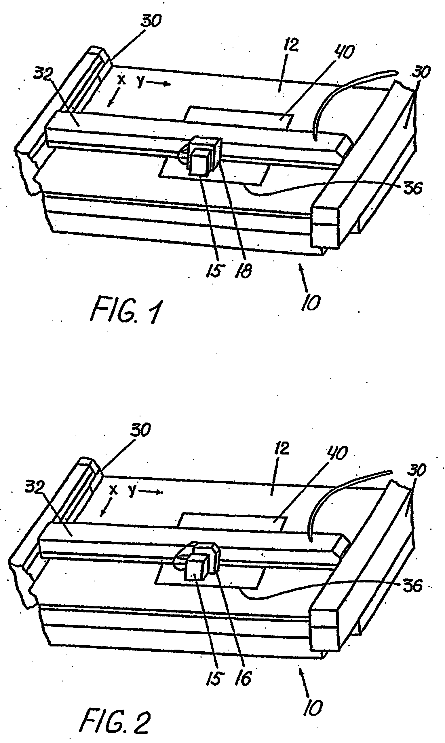
[0059]Referring to FIGS. 1 and 2, fray-free cutting apparatus 10 includes a textile-receiving surface 12, a controller 14 having programmed information regarding perimeter 44 of an area 42, a cutter 16 movable with respect to surface 12 as directed by controller 14 to cut a textile sheet 40 at perimeter 44 of area 42, and an anti-fray instrument 18 movable with respect to surface 12 as directed by controller 14 based on the programmed information to form an anti-fray path 46 along perimeter 44. Apparatus 10 may further include a vacuum structure 36 adapted to retain textile sheet 40 in position on textile-receiving surface 12.

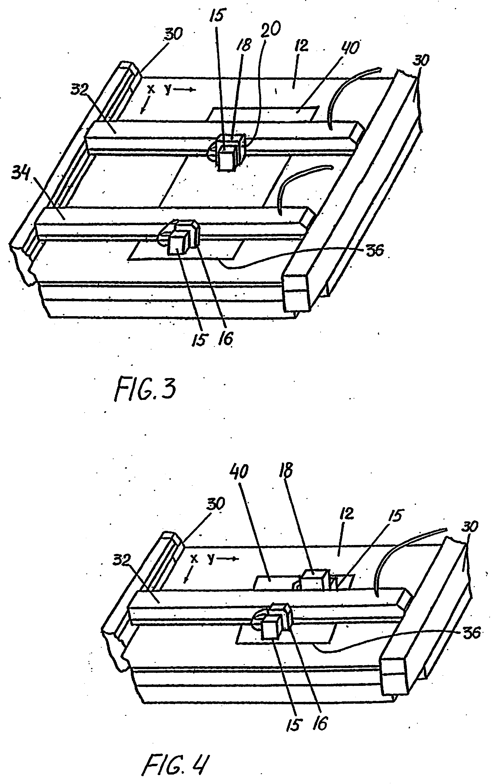
[0060]As shown in FIGS. 1-8 the fray-free apparatuses include support structure 30 secured with respect to textile-receiving surface 12. Anti-fray instrument 18 is attached to support structure 30 for controlled movement along textile-receiving surface 12.

[0061]As best shown in FIG. 1, support structure 30 includes a beam 32 which spans textile-receiving surfac...


PUM

PropertyMeasurementUnit
widthaaaaaaaaaa
perimeteraaaaaaaaaa
softening pointaaaaaaaaaa

Abstract

A method and apparatus for fray-free cutting at the perimeter of an area of a textile sheet on a textile-receiving surface, including creating an anti-fray condition in the sheet along a path at the perimeter by an anti-fray instrument movable along the surface as directed by a controller based on programmed information regarding the perimeter, and cutting the sheet at the perimeter by a cutter movable along the surface as directed by the controller based on the programmed information. The anti-fray instrument is preferably an anti-fray substance applicator or, if the textile is a thermoplastic textile, a laser device configured and arranged to induce an anti-fray state therein.

Description

RELATED APPLICATION[0001]This application is a continuation-in-part of patent application Ser. No. 11 / 398,335, filed Apr. 5, 2006, currently pending. The contents of the parent application are hereby incorporated by reference.FIELD OF THE INVENTION[0002]The invention is related generally to the field of textile processing technology and more particularly to fray-free cutting of textiles or the like for various purposes.BACKGROUND OF THE INVENTION[0003]Many textile materials of woven or non-woven nature tend to fray when cut into pieces or shapes and subsequently handled during various operations. It is highly desirable that the cutting of textiles be carried out in a manner preserving the cut edges from fraying or other similar degradation. Indeed, advantages of precision cutting tend to be lost due to fraying and other edge-related concerns.[0004]The prior art includes a number of disclosures of applying liquid polymeric materials for purposes of avoiding textile fraying, or for pi...

Claims


Application Information

Patent Timeline
Patent Type & Authority Applications(United States)
IPC IPC(8): B26D7/06B26D1/00
CPCB26D7/08B26D7/34Y10T156/12D06H7/00Y10T156/1052B26F1/3813D06C25/00Y10T83/0443Y10T83/0491Y10T83/263Y10T83/727
Inventor MIKKELSEN, STEEN B.
Owner MIKKELSEN GRAPHIC ENG
Why Eureka
Try Eureka