Dishwasher having steam washing function and dishwashing method

a technology of dishwashing and steam washing, which is applied in the direction of washing process, washing using liquids, couplings, etc., can solve the problems of food particles and dried substances that cannot be removed sufficiently, and the dish is not solidly attached to the surfa

Inactive Publication Date: 2007-10-11
SAMSUNG ELECTRONICS CO LTD
View PDF11 Cites 40 Cited by
  • Summary
  • Abstract
  • Description
  • Claims
  • Application Information

AI Technical Summary

Benefits of technology

[0027]Assuming that one of the stationary and movable steam supply pipes is inserted into the other steam supply pipe, the coupling structure comprises a groove formed at an outer peripheral surface of the steam supply pipe to be inserted into the other steam supply pipe, a

Problems solved by technology

A conventional water dishwashing has problems sufficiently removing food particles and substances that are dried and solidly adhered to dishes.
However, the prior art dishwashers cannot inject steam directly to dishes to wash the dishes usi

Method used


Image

  • Dishwasher having steam washing function and dishwashing method
  • Dishwasher having steam washing function and dishwashing method
  • Dishwasher having steam washing function and dishwashing method

Examples


first embodiment

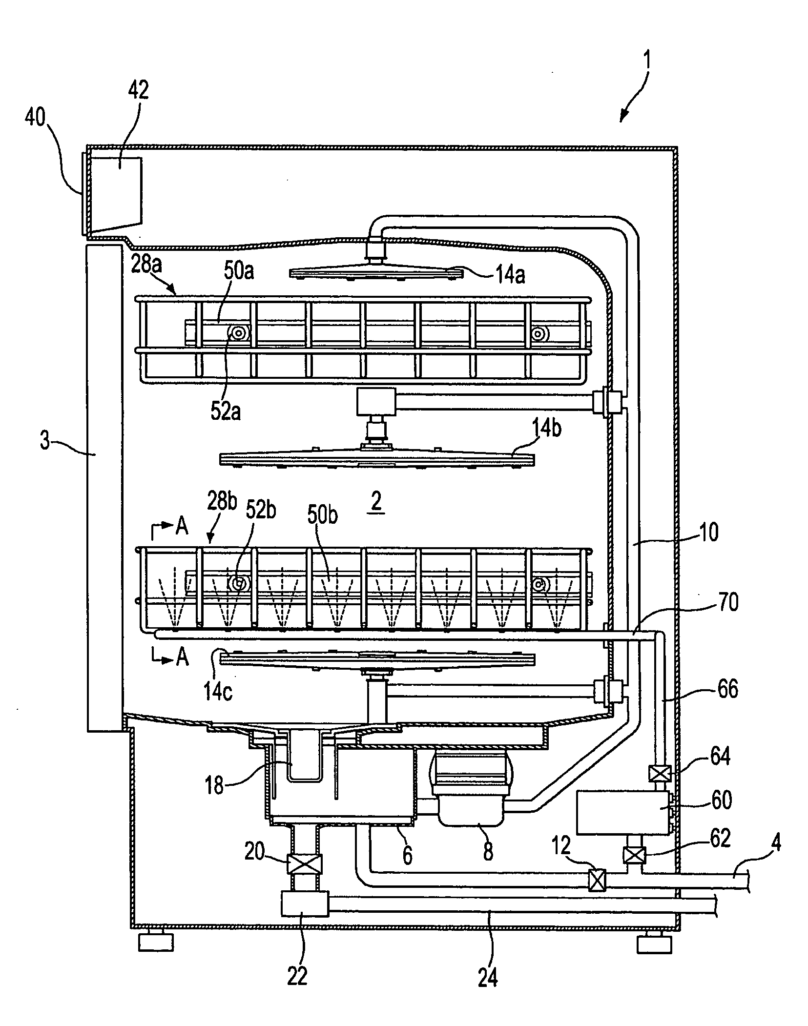
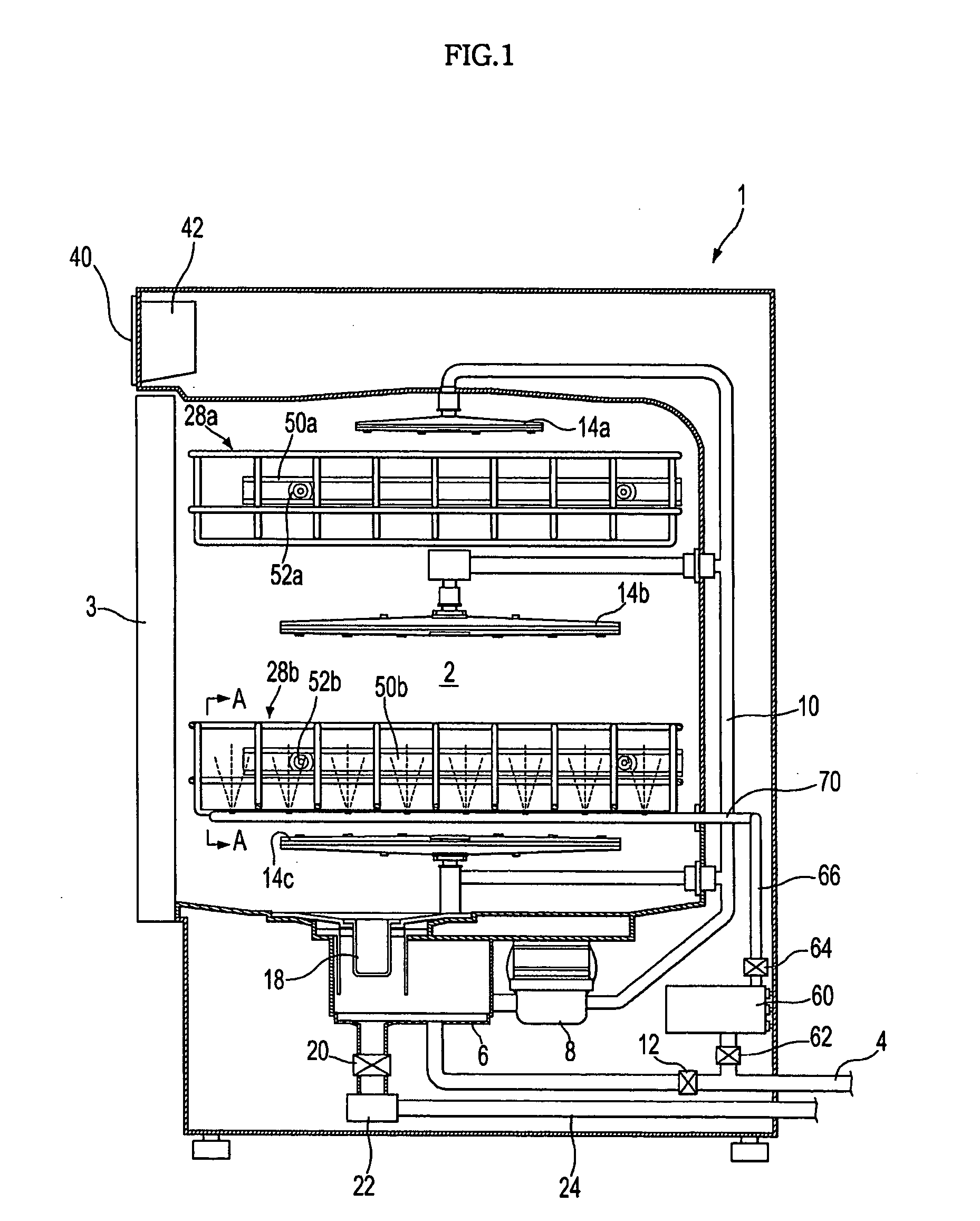
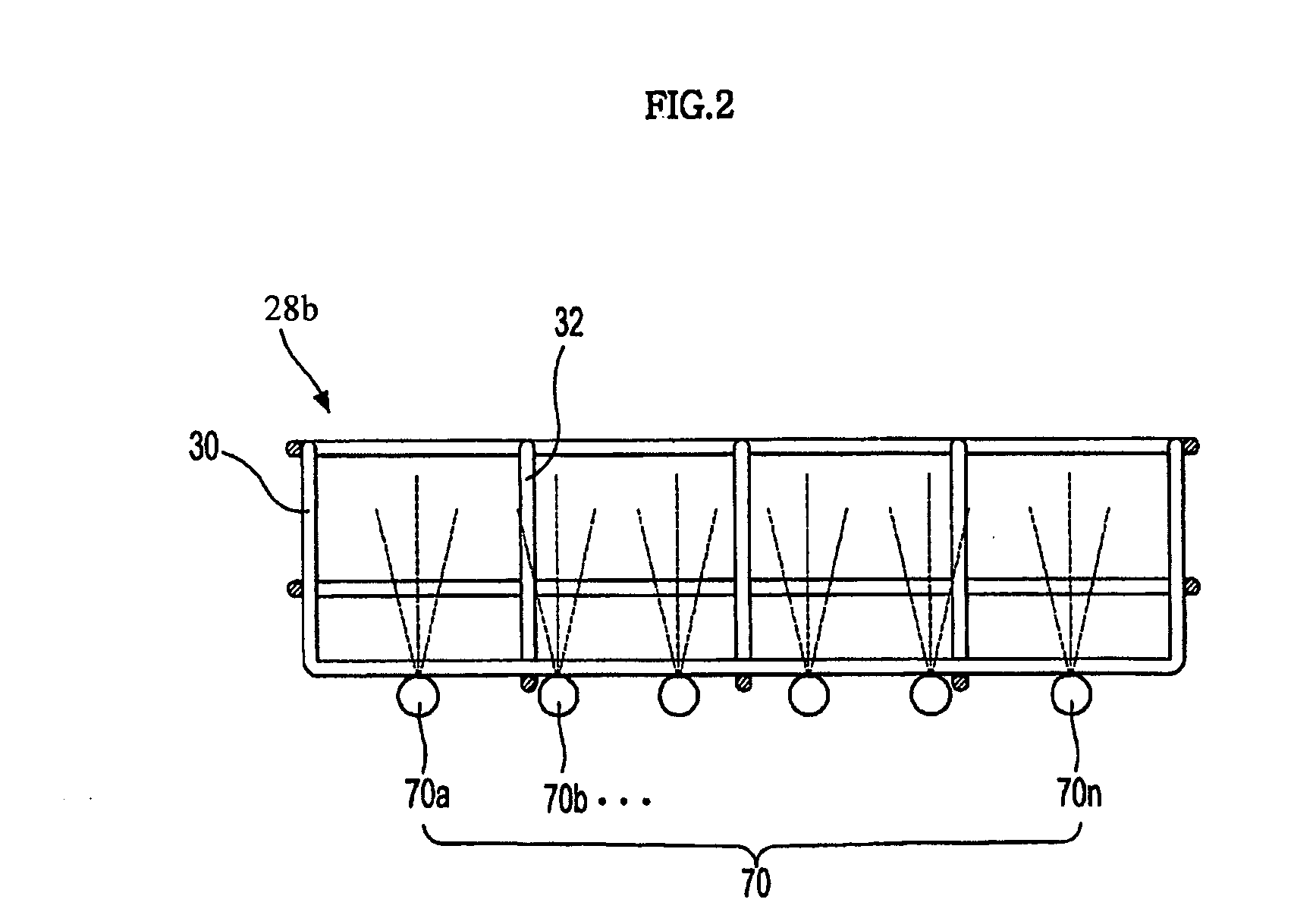
[0053]FIG. 1 is a sectional view showing a dishwasher according to the present invention. As shown in FIG. 1, the dishwasher includes a body 1, a forwardly open dishwashing tub 2 received in the body 1, and a door 3 hingedly coupled to a front side of the body 1 to open and close a front opening of the dishwashing tub 2. The dishwashing tub 2 contains upper and lower dish baskets 28a and 28b, which are mounted at appropriately determined upper and lower locations of the dishwashing tub 2 to receive dishes therein. The dish baskets 28 (28a and 28b) are externally provided with rollers 52a and 52b, respectively, such that the dish baskets 28a and 28b are disposed, in a slidingly movable manner, on upper and lower rails 50a and 50b, which are mounted at opposite inner sidewalls of the dishwashing tub 2. Of course, other various configurations for forward and rearward sliding movements are also possible.

[0054]A plurality of water injection nozzles 14 (14a, 14b and 14c) are mounted at po...

second embodiment

[0079]With the configuration and control method of the second embodiment, a steam injection pressure at the steam injection holes 75 of the respective steam injection nozzles 70 can be increased greatly as compared to steam supplied into the respective steam injection nozzles 70 in only one injection, to a level sufficient to be directly utilized for dishwashing.

[0080]Specifically, pressure of steam is a factor having a large effect on dishwashing performance, and thus, good dishwashing results are obtained when the pressure of steam being injected from each steam injection hole is greater than a predetermined pressure.

[0081]FIG. 11 is a graph showing the relationship between the number and diameter of steam injection holes and the pressure of steam being injected from the steam injection holes, which is obtained as a result of experiment. A steam generator used in the above experiment has a capacity capable of generating steam having a pressure of 6 bar, a flow rate of 200 cc / min, ...


PUM


Abstract

A steam/water mixed dishwasher using steam and water together, and, more particularly, a dishwasher and dishwashing method of achieving improvement in washing performance and efficiency via direct steam injection to dishes. The dishwasher includes a body containing a dishwashing tub, at least one dish basket disposed in the dishwashing tub and adapted to receive dishes therein, a steam generator to generate steam by heating wash water, and steam injection nozzles to inject the steam generated from the steam generator. The steam injection nozzles are disposed at the same height as a lower surface of the dish basket. The dishwashing method includes injecting steam from a number of the plurality of steam injection nozzles by opening a number of the plurality of control valves, to thereby maintain an injection pressure of the steam generated from the steam generator.

Description

CROSS-REFERENCE TO RELATED APPLICATIONS[0001]This application claims the benefit of Korean Patent Application No. 10-2006-0031986, filed on Apr. 7, 2006 in the Korean Intellectual Property Office, the disclosure of which is incorporated herein by reference.BACKGROUND OF THE INVENTION[0002]1. Field of the Invention[0003]The present invention relates to a steam / water mixed dishwasher, which is designed to use steam and water together, and, more particularly, to a dishwasher and dishwashing method, which can achieve a steam dishwashing by injecting steam directly to dishes.[0004]2. Description of the Related Art[0005]Generally, a dishwasher is an apparatus to inject cold or hot water to dishes, which are disposed in a dish basket inside a dishwashing tub, for removing contaminants adhered to the dishes. The dishwasher includes several devices, such as a pump and nozzles to inject wash water, and a heater, etc. to generate hot water.[0006]In a recent technology, steam as well as water h...

Claims


Application Information

Patent Timeline
IPC IPC(8): B08B9/20B08B3/00
CPCA47L15/0015A47L15/4234A47L15/4278A47L15/50F16L37/23A47L2601/04B05B1/20F16L37/086A47L15/508A47L15/42A47L15/12A47L15/00
Inventor LEE, CHANG HUIKIM, GYOUNG ROKRYU, JUNG CHANIMM, SO JUNGYANG, DONG YOLBAE, JOONG MYEONRYU, SEUNG MINYUN, CHONG BAELIM, SUNG KWANGKO, TAE HYUNJO, HYUNKIM, HYUN-HOLEE, HYANG JUN
Owner SAMSUNG ELECTRONICS CO LTD
Why Eureka
Try Eureka